Terminal module
a terminal module and module technology, applied in the direction of coupling contact members, coupling device connections, electrical devices, etc., can solve the problems of inability to utilize large-current applications, inability to conduct, and configuration of japanese unexamined patent publication no. 2002, 274290
- Summary
- Abstract
- Description
- Claims
- Application Information
AI Technical Summary
Benefits of technology
Problems solved by technology
Method used
Image
Examples
first embodiment
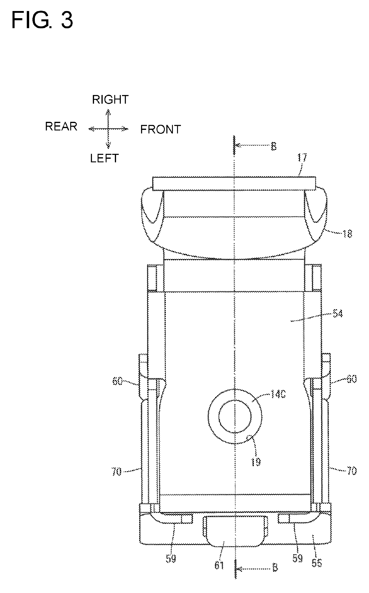
[0036]A first embodiment is described with reference to FIGS. 1 to 8. In the following description, a vertical direction and a lateral direction are based on a vertical direction and a lateral direction in FIG. 1. Further, a front-rear direction is based on a direction perpendicular to the plane of FIG. 1, wherein a side in front of the plane is referred to as a front and a side behind the plane is referred to as a rear.
(1-1) Connector
[0037]As shown in FIG. 1, a connector 40 is fit and connected electrically to a mating connector 2 and includes a terminal fitting 50 (an example of a terminal module) and a housing 51 for accommodating the terminal fitting 50.
[0038](1-1-1) Terminal Fitting
[0039]The terminal fitting 50 includes a metal case 52, a cylindrical spring receiving portion 14 crimped to a ceiling wall 54 of the metal case 52, a plate-like electrical contact 53, a coil spring 16 (an example of a resilient member) accommodated in the metal case 52 while being compressed by the ...
second embodiment
[0079]A second embodiment is described with reference to FIGS. 9 to 15.
(2-1) Connector
[0080]As shown in FIG. 9, a connector 201 according to the second embodiment also is fit and connected electrically to a mating connector 2 and includes a terminal fitting 210 (an example of a terminal module) and a housing 211 for accommodating the terminal fitting 210.
[0081](2-1-1) Terminal Fitting
[0082]The terminal fitting 210 includes a metal case 212, a spring receiving portion 14, an electrical contact 215, a coil spring 216, an intermediate terminal 217 and a braided wire 218.
[0083]As shown in FIGS. 10 to 12, the metal case 212 is formed by press-working a metal plate material, such as a SUS material, and is formed into a substantially box shape with a ceiling wall 213 and two side walls 220 extending down from both front and rear ends of the ceiling wall 213 and parallel to each other, and includes openings on left, right and lower sides. The opening 221 (see FIG. 12) on the lower side is a...
third embodiment
[0103]A third embodiment is described with reference to FIG. 16.
[0104]The third embodiment is a modification of the second embodiment. In the second embodiment described above, the first folded portion 224A (first guide) and the second folded portion 224B (second guide) are substantially parallel. In contrast, as shown in FIG. 16, a second folded portion 324A (second guide) is inclined more than a first folded portion 324A (first guide) in a terminal fitting 310 according to the third embodiment.
[0105]Thus, an interval H31 in a horizontal direction between the first and second folded portions 324A and 324B at a movement end position of an electrical contact 215 in a vertical direction (an example of the inserting direction of the mating contact point) is wider than an interval H32 in the horizontal direction between the first and second folded portions 324A and 324B at a position before moving up by being pressed by a mating contact point 31 (i.e. position before a movement).
[0106]T...
PUM
 Abstract
Description
Claims
Application Information
 - R&D
- Intellectual Property
- Life Sciences
- Materials
- Tech Scout
- Unparalleled Data Quality
- Higher Quality Content
- 60% Fewer Hallucinations
Browse by: Latest US Patents, China's latest patents, Technical Efficacy Thesaurus, Application Domain, Technology Topic, Popular Technical Reports.
© 2025 PatSnap. All rights reserved.Legal|Privacy policy|Modern Slavery Act Transparency Statement|Sitemap|About US| Contact US: help@patsnap.com


