
Construction framing system and track therefor

Inactive Publication Date: 2005-06-16
674249 B C
View PDF30 Cites 11 Cited by
  • Summary
  • Abstract
  • Description
  • Claims
  • Application Information

AI Technical Summary

Benefits of technology

[0040] Yet another aspect of the invention provides a method for accommodating relative movement between a track and one or more studs in a building framing system. The method involves a track having a web which extends in a longitudinal direction and one or more legs which extend from the web and which extend along at least a portion of the web in the longitudinal direction. The method comprises rigidly coupling first ends of the one or more studs to the one or more legs and deforming the one or more legs to permit relative movement of the one or more studs toward the web and / or away from the web.

Problems solved by technology

The rigid connections of such framing systems do not allow relative movement between the framing system components.
This rigidity presents a serious problem in some circumstances.
For example, rigid framing systems can be damaged if there is any relative movement of the building structure components between which the framing systems are mounted.
Under varying load conditions, pressure and forces can weaken and damage the framing system and / or the building structure and can cause cracks in the wall coverings, which are unsightly, unsafe and which may lead to further damage to the framing system and / or the building structure.
The framing systems disclosed in these patents have a number of disadvantages, which include, for example: requiring additional “slip tracks” positioned between the vertical studs and the horizontal tracks; requiring clip components and / or stud extension members located and / or connected between the horizontal tracks and the vertical studs; requiring complex-shaped, difficult to fabricate studs or tracks; and requiring slotted tracks penetrated by fasteners or other projections.
Some of these framing systems require relatively costly components and relatively large amount of installation time.
In addition, some of these prior art systems permit an undesirably small amount of movement of the studs relative to the tracks.

Method used


Image

  • Construction framing system and track therefor
  • Construction framing system and track therefor
  • Construction framing system and track therefor

Examples


Embodiment Construction

[0059] Throughout the following description, specific details are set forth in order to provide a more thorough understanding of the invention. However, the invention may be practiced without these particulars. In other instances, well known elements have not been shown or described in detail to avoid unnecessarily obscuring the invention. Accordingly, the specification and drawings are to be regarded in an illustrative, rather than a restrictive, sense.

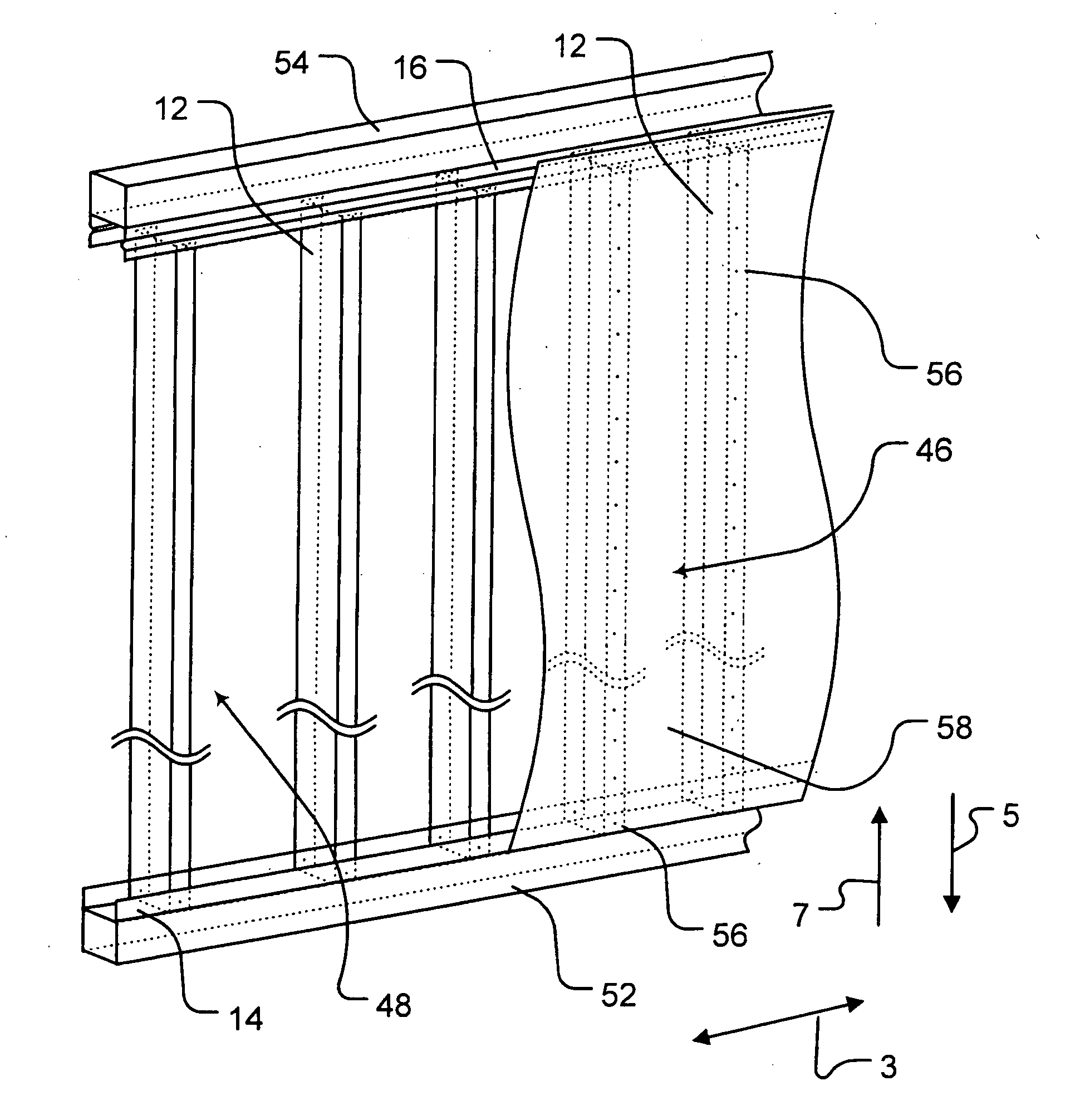
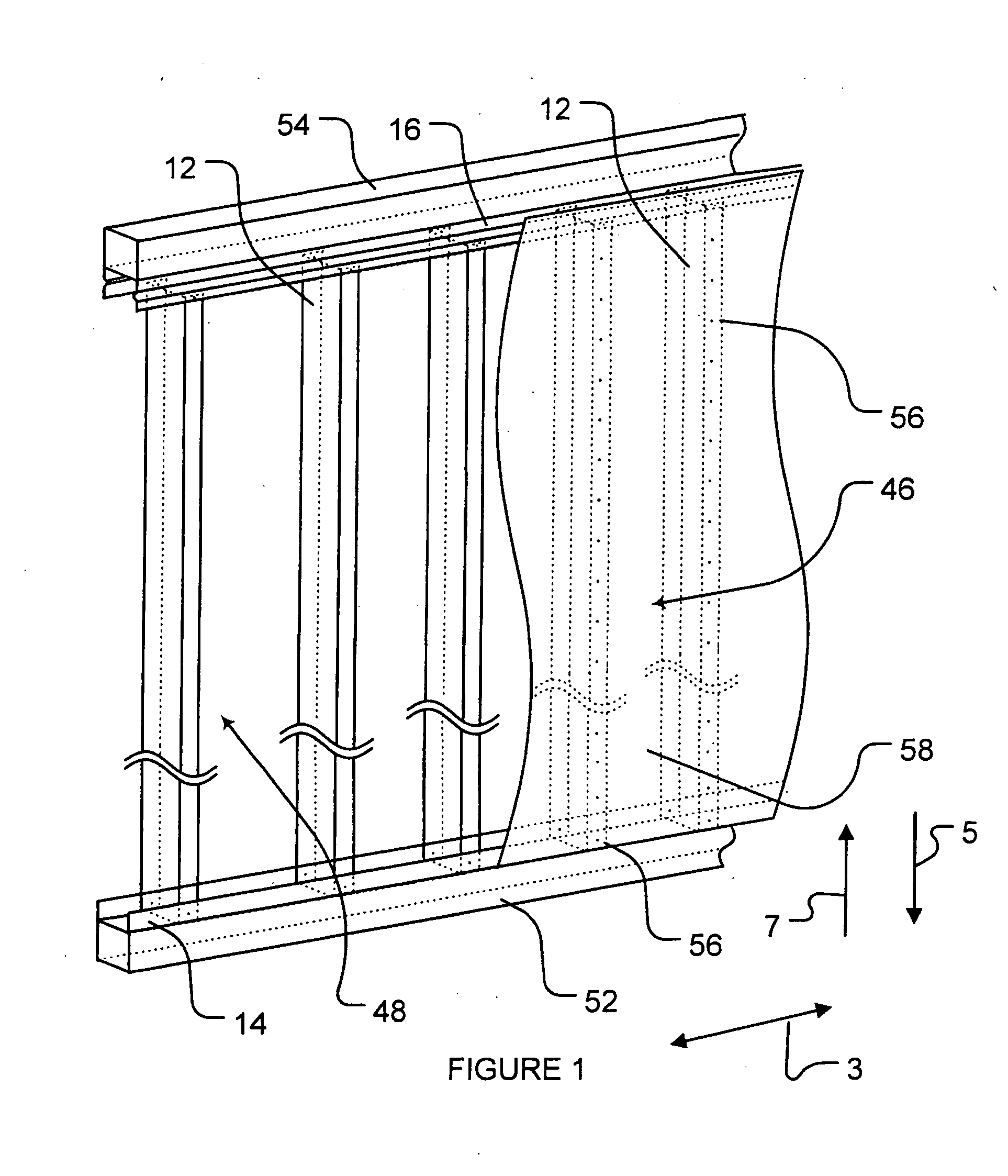
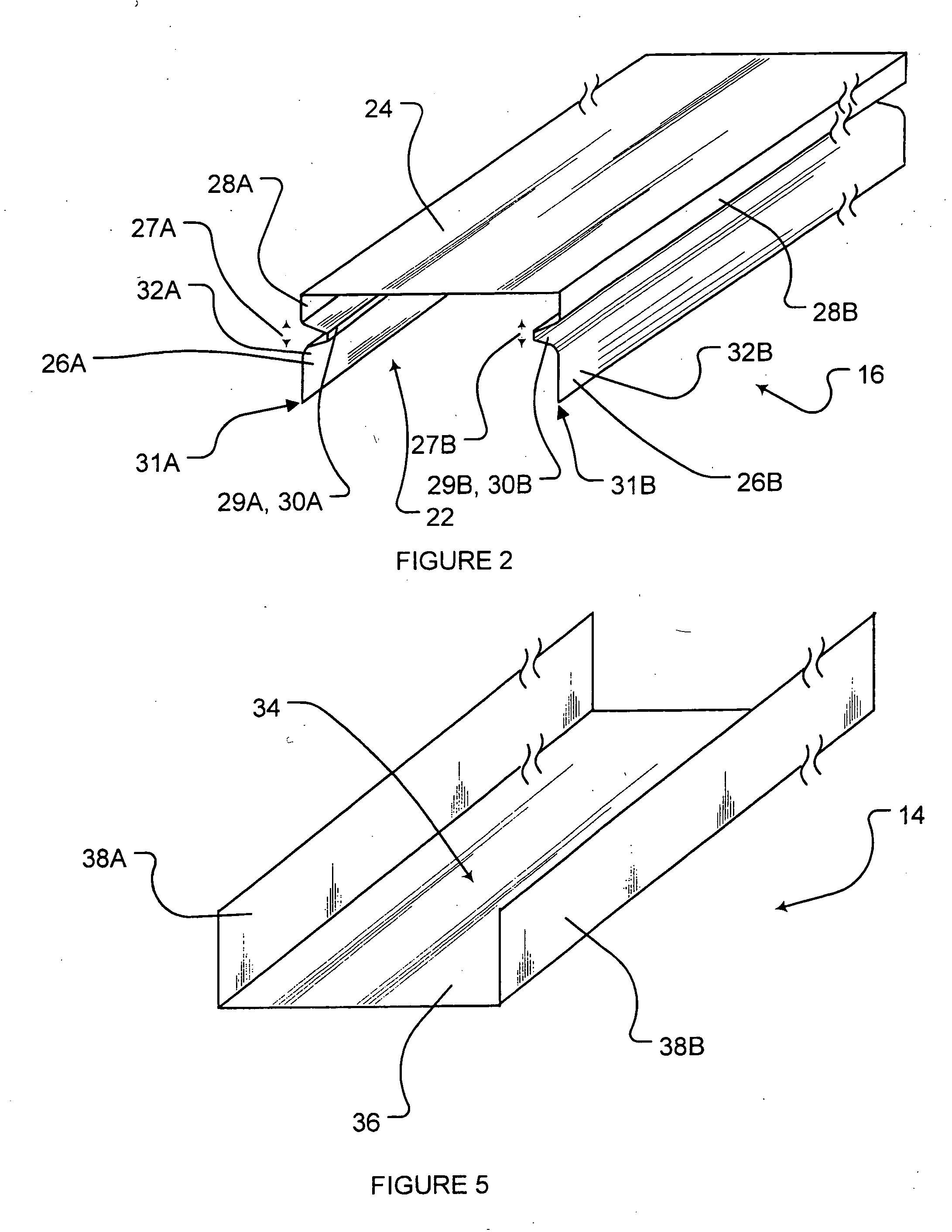
[0060] Aspects of this invention relate to framing systems for use in construction of buildings and other structures and to tracks for use in such framing systems. Such framing systems may support interior and / or exterior wall coverings. Framing systems according to the invention are designed to accommodate relative movement between components of the building structure. More specifically, tracks are provided with one or more deformable legs, such that relative movement between building structure components may be accommodated by exp...


PUM


Abstract

A framing system for use in a building structure includes a track having a longitudinally-extending web and a pair of spaced apart legs which extend from the web to form a channel between the web and the legs. One or more longitudinally-extending studs are coupleable to the legs of the track. Each leg of the track comprises a deformable portion, the deformation of which is accompanied by movement of the one or more studs toward or away from the web.

Description

TECHNICAL FIELD [0001] The invention relates to the field of construction. Particular embodiments of the invention relate to framing systems for use in construction of buildings and other structures. BACKGROUND [0002] Framing systems having components made of metal, typically steel or other alloys, referred to as “steel stud” framing systems, are currently used in many industrial and commercial buildings and in an increasing number of residential buildings. Steel stud framing systems have several advantages over conventional wooden framing systems including reduced environmental concerns, fire safety and freedom from warpage, insect damage and rot. Typical steel stud framing systems incorporate horizontal tracks and vertical studs which support interior and / or exterior wall coverings. Typical wall coverings include drywall panels, stucco panels and the like. These wall coverings are usually secured to the studs of the framing system by suitable fasteners. Typically, wall coverings a...

Claims


Application Information

Patent Timeline
IPC IPC(8): E04B2/76E04B2/78E04B2/82E04C3/04E04C3/07E04C3/09E04C3/29
CPCE04B2/767E04B2/7854E04B2/789E04B2/82E04C2003/0473E04C3/09E04C3/29E04C2003/0413E04C2003/0421E04C3/07
Inventor ERICKSON, DENNISTAYLOR, KEITH
Owner 674249 B C
Learn More