Method and device for controlling robot

a robot and robot control technology, applied in the field of robot control methods and devices, can solve the problems of robot robots no longer being able to control themselves, and robots no longer being able to move, so as to reduce overconstraints on parts, increase the working volume of the robot, and increase the range of each robot.

Active Publication Date: 2005-06-09
KUKA ROBOTER
View PDF15 Cites 11 Cited by
  • Summary
  • Abstract
  • Description
  • Claims
  • Application Information

AI Technical Summary

Benefits of technology

[0034] Removing the requirement for one or more DOF of orientation control also frees at least one DOF for redundant solutions for each robot, meaning a robot is free to reach a given location in more than one way (using an arbitrary orientation). This can be used to help avoid singularities in load sharing.
[0036] By relaxing the orientation requirement of each robot, according to the invention, the working volume of that robot is increased (by permitting it to move into non-dexterous areas of its working volume) and the over-constrained situation with the part is reduced. Though this does not remove interference between robots in all cases, it may reduce the interference regions by permitting the robots to reach their grip points in different orientations.
[0043] The inventive algorithm for determining the orientation of each robot sharing the load is called a “minimum extension” solution. By minimizing the distance from the base of the robot to its Wrist Center Point (WCP) for each point along a trajestory, the WCP is permitted to go farther along the trajestory, thus maximizing the working volume. This minimum extension approach can be used for the WCP, because a particular orientation has not be satisfied. That is, for each point along the trajestory, the orientation of the Tool Center Point (TCP) is permitted to change such that the WCP is closer to the robot base than if the specified orientation were used. The algorithm finds a solution that:

Problems solved by technology

This is because the robots can interfere with each other in various orientations of the part, and because the two or more robots are not located in the same place.
That is, two robots grasping a part may break the part or themselves, because they each try to fix all 6 DOF.
This also means that there is an axis of rotation about which the robot no longer can move.
Usually, if trying to keep constant TCP speed, the wrist joints will try to move faster than their limits, and the TCP either has to slow down, or the robot must leave the desired trajectory, or the robot just stops because of a speed limit error.
The problem is even more disastrous when two or more robots are carrying the same part and one of them moves near a singular position.
This is difficult to do in such a way that there is no strain on the part.
This is because the robots can interfere with each other in various orientations of the part, and because the robots are not located in the same place.

Method used


Image

  • Method and device for controlling robot
  • Method and device for controlling robot
  • Method and device for controlling robot

Examples


Embodiment Construction

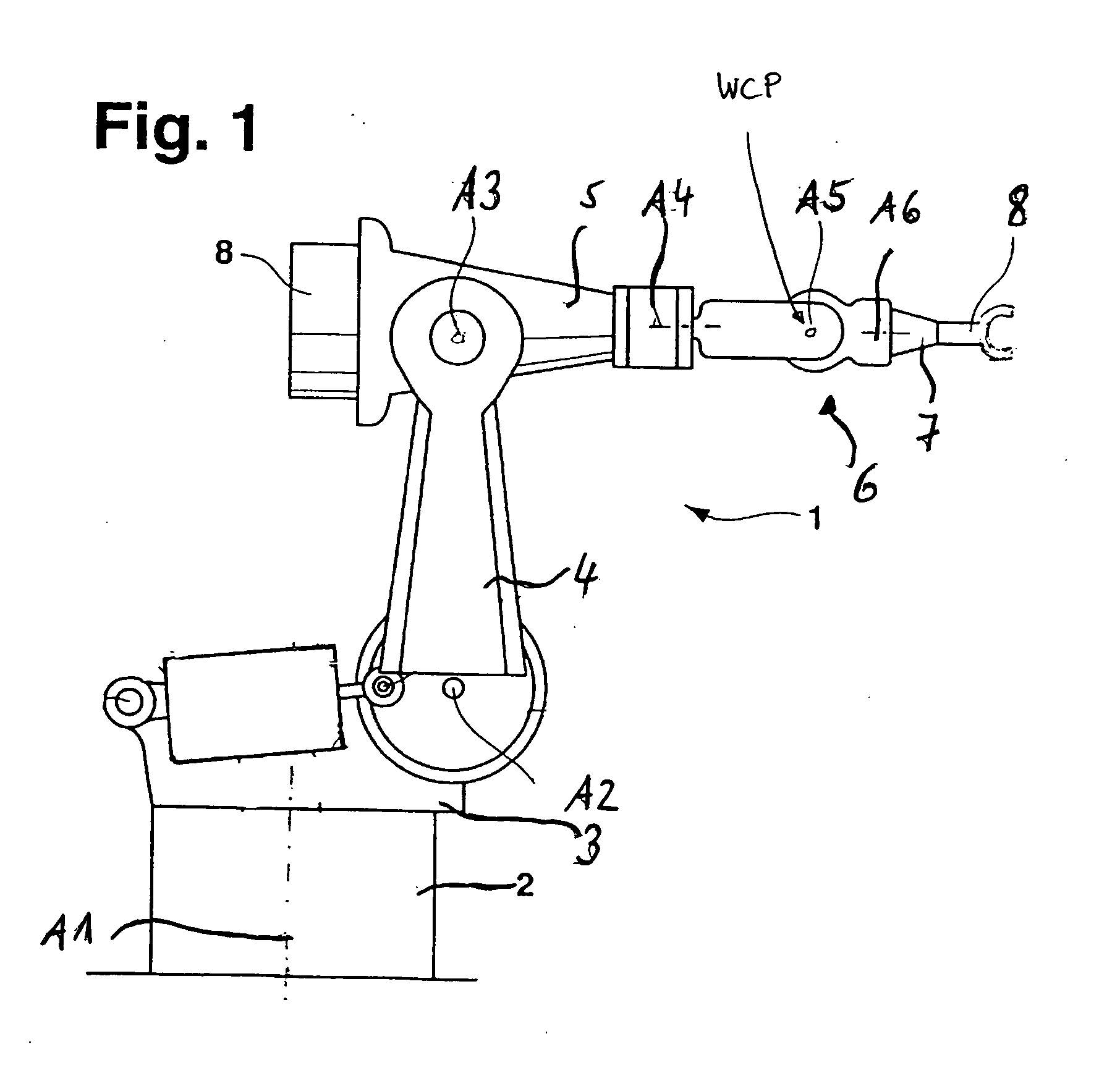
[0059] An inventive industrial robot according has a fixed base 2 carrying a roundabout 3 pivotable about a vertical A1-axis. A first robot arm 4 is pivotably about a horizontal A2-axis connected with the roundabout 3.

[0060] The first robot arm 3 carries, pivotable about an horizontal A3-axis a second robot arm 5. The arm 5 has attached to it a robot hand 6, having three parts each of them being pivotable about an axis A4, A5, and A6, respectively. The axes intersect at the axis A5, which is the wrist center point (WCP) for this particular robot design. The free end of the hand part 7 (pivotable about the A6-axis) is provided with a tool 8, in this embodiment of the invention with a socket of a ball-socket-joint.

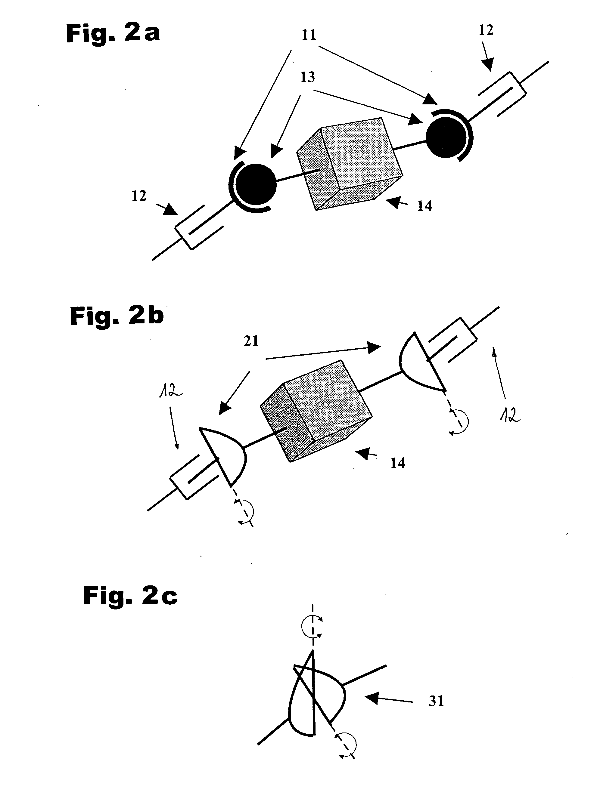
[0061] When a workpiece is carried by a single industrial robot a gripper is used that constrains the part in 6 DOF (x, y, z location and rotations about x, y, z).

[0062]FIG. 2a shows attachment to a part 14 by a ball-and-socket joint with e.g. a socket 11 connected to the...


PUM

PropertyMeasurementUnit
Degrees of Freedomaaaaaaaaaa
rotationaaaaaaaaaa
trajectoryaaaaaaaaaa

Abstract

A method for controlling a robot during an interpolation of a trajectory or motion to any prescribed position, comprises the steps of a) ignoring at least one of the three originally prescribed or interpolated tool center point orientation values; b) finding new tool center point orientation values that place the wrist center point of the robot closest to its base while c) maintaining the originally prescribed or interpolated tool center point location values and d) maintaining the original prescribed or interpolated tool center point orientation values not ignored. Said method can preferably be used for carrying a load with a plurality of robots. Its main advantage is an increase of the available working volume.

Description

BACKGROUND OF THE INVENTION [0001] The invention relates as well to a method and a device for controlling at least one robot as to a method and a device of carrying a load with more than one robot. [0002] It is known that in some cases, when two or more robots carry a part (load sharing), the total working volume may be reduced for the part over that achievable by carrying the part with a single robot. This is because the robots can interfere with each other in various orientations of the part, and because the two or more robots are not located in the same place. Therefore, a trajectory that is achievable by one robot is sometimes not also achievable by the others. [0003] At the same time it is well known that the dexterous working volume of a robot (the volume in which all orientations can be reached) is usually less than the non-dexterous working volume. [0004] Orientation of the part in load sharing is dictated by only the location of the grip points of the individual robots. The...

Claims


Application Information

Patent Timeline
Patent Type & Authority Applications(United States)
IPC IPC(8): B25J9/16
CPCB25J9/1607B25J9/1682G05B2219/40333G05B2219/39109G05B2219/39069
Inventor STODDARD, KENNETH A.MARTIN, DAVID
Owner KUKA ROBOTER
Why Eureka
Try Eureka