Hinged socket wrench speed handle

Inactive Publication Date: 2005-06-09
ANDERSON STEVEN P
View PDF9 Cites 190 Cited by
  • Summary
  • Abstract
  • Description
  • Claims
  • Application Information

AI Technical Summary

Benefits of technology

[0013] In today's economy manpower is expensive and any tool or device that can reduce the time spent accomplishing a given task is of extreme importance. Therefore, the primary object of the invention is to provide a hand tool that can be utilized with most popular socket sets, and that shortens the time required to attach or remove a threaded fastener with a polygon-shaped or other configured head on a screw, bolt or nut. Normally, a ratchet handle is connected to a socket and ratcheted by radial motion with one hand while being held in place with the other hand. The instant invention permits a user to rapidly rotate the nut or bolt until it starts to tighten. The rapid rotation is accomplished by simple wrist action, with considerably more speed than a conventional ratchet handle. By testing, it was determined that by using the instant invention, the tightening or removal of a fastener, after its initial loosening, was four to five times faster than accomplished previously.
[0015] Another object of the invention is directed to a unique locking system that secures either the square drive head or the ratchet drive head at a given angle relative to the handle. This feature is particularly useful when the tool is used like a “bull handle” or an “L-handle”. Further, the arrangement locks the head at equal angular increments, which are at the most convenient positions. It should also be noted that it is not necessary to lock the head, as it rotates under a small amount of tension and is temporarily held at the angular displacement by a spring-loaded detent 50 it can be controlled during operation. Locking is easily and intuitively obvious by simply pressing a hinge pin in one direction or the other for positive positioning at the 45 degree increment.

Problems solved by technology

In today's economy manpower is expensive and any tool or device that can reduce the time spent accomplishing a given task is of extreme importance.
Conventional speed handles are long and have limited utility as unrestricted space is essential to their function.

Method used


Image

  • Hinged socket wrench speed handle
  • Hinged socket wrench speed handle
  • Hinged socket wrench speed handle

Examples


Embodiment Construction

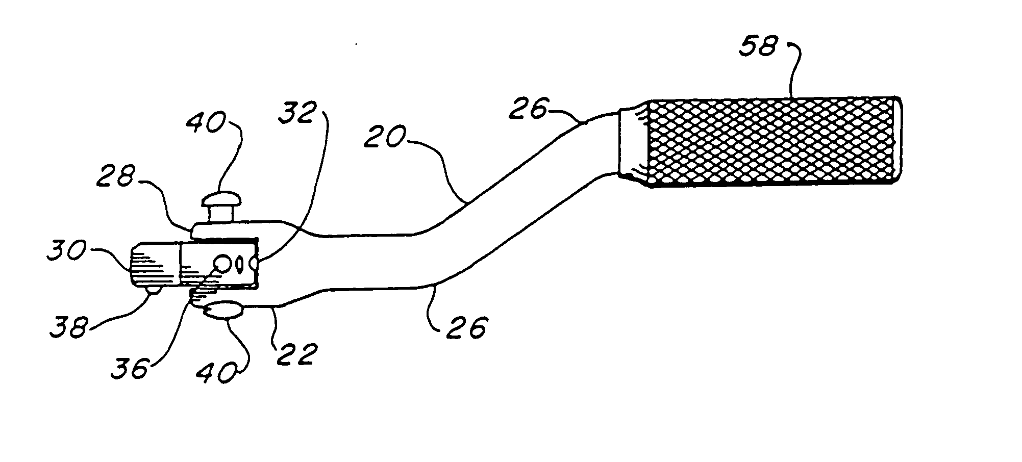
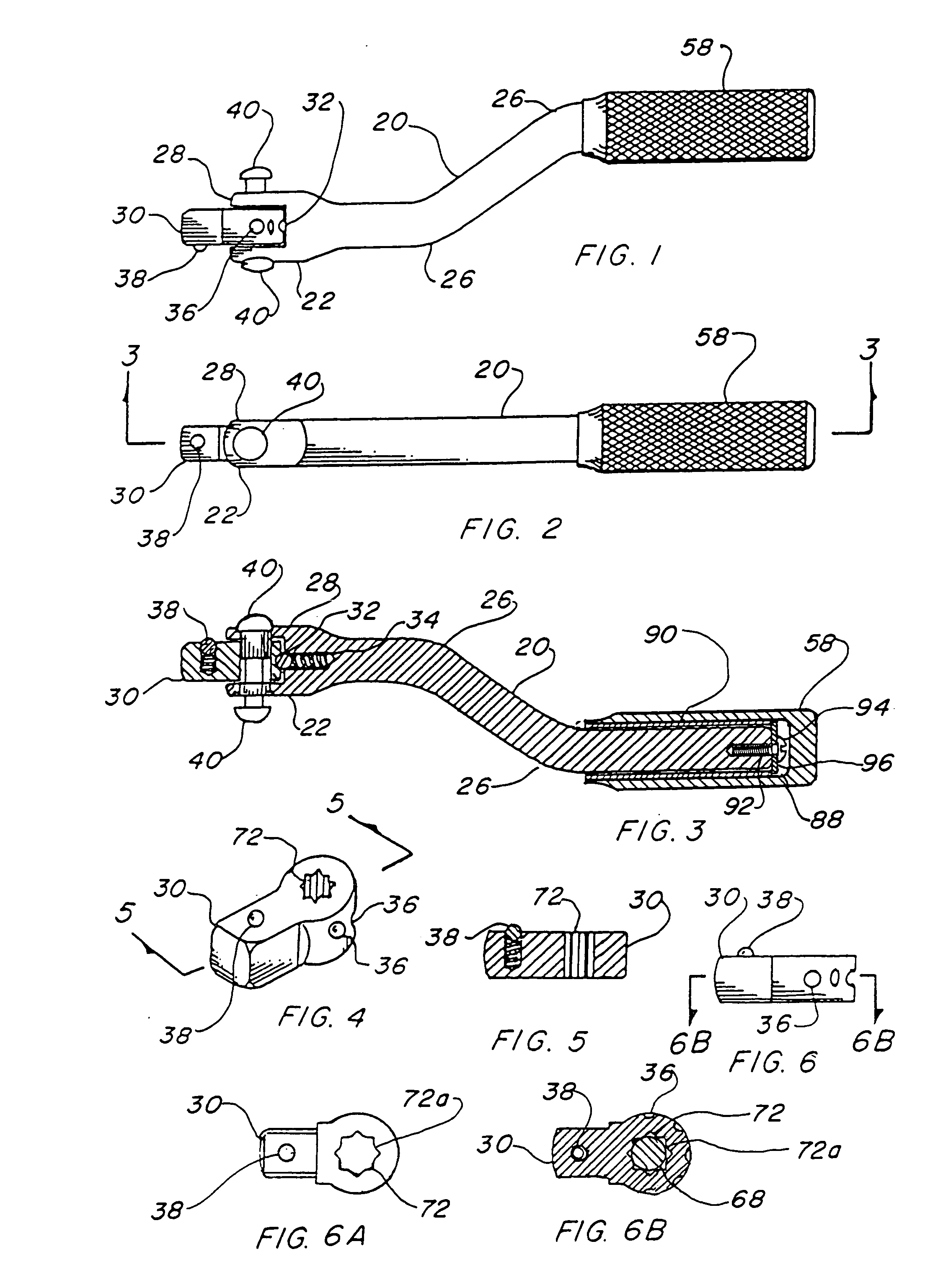
[0063] The best mode for carrying out the invention is presented in terms of a preferred embodiment and a second embodiment for a hinged socket wrench speed handle. Both embodiments are alike except the second embodiment has an additional pivoting head on the end of the offset shank adjacent to the handle. The preferred embodiment is shown in FIGS. 1 through 23, with the single pivoting head shown in FIGS. 1, 2, 3, 11, 21 and 22, and the second embodiment with the additional pivoting head shown in FIGS. 12, 13, 17, 18, 19, 20 and 23.

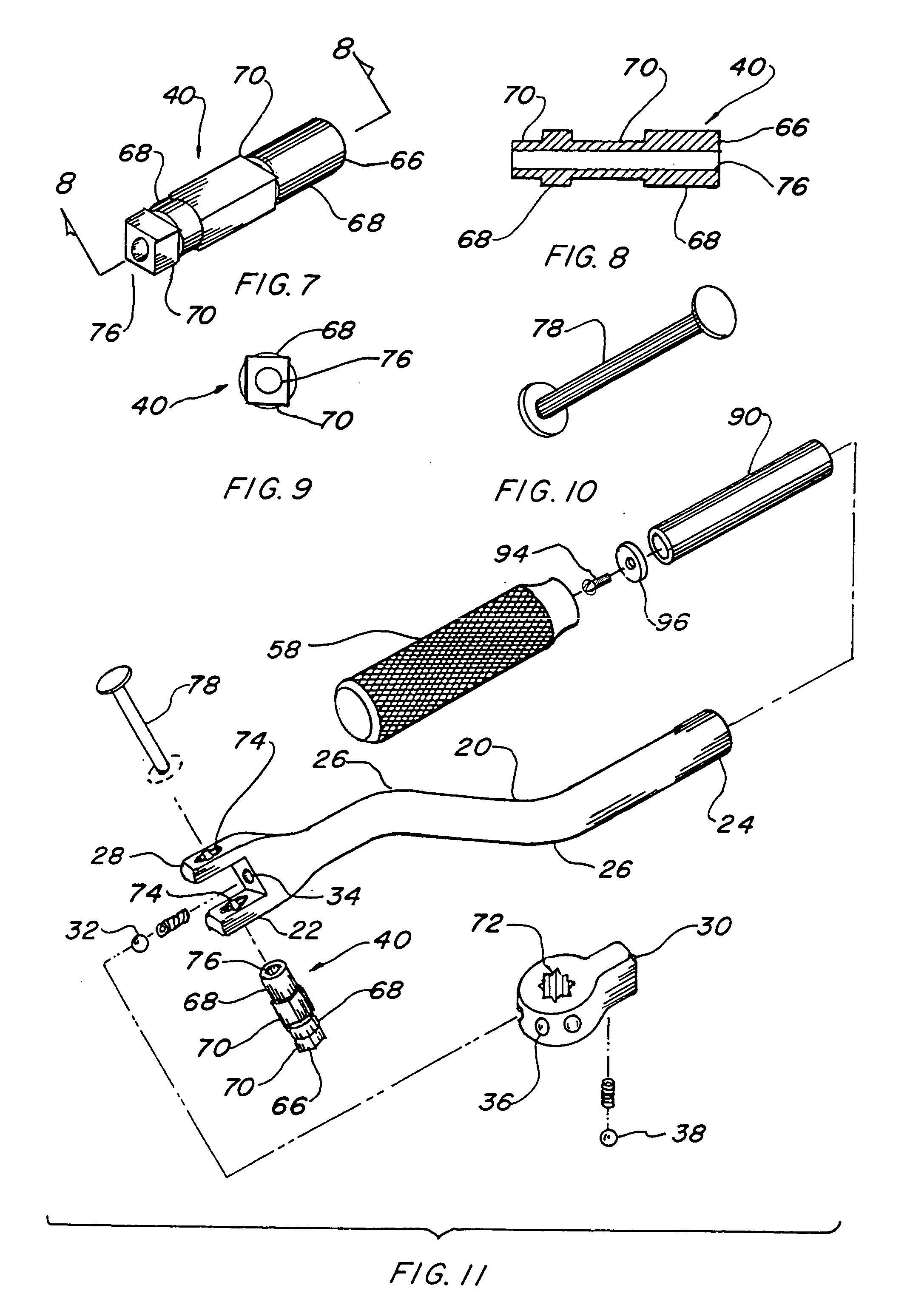
[0064] The offset shank 20, in either embodiment, which may be round in shape and made of metal, has a first end 22, a second end 24, and two opposed bends 26 that are integrally formed or forged during fabrication. The bends 26 are of equal angles from 10 degrees to 90 degrees, with 45 degrees being preferred, and the first end 22 and second end 24 are parallel in each opposed direction, as illustrated in FIGS. 1, 3 and 11. A clevis 28 is integrally fo...


PUM


Abstract

A hinged socket wrench having an offset shank (20) with a first end (22) and a second end (24). Attached to the first end (22) is a clevis (28) which receives a 180-degree drive head held by a hinge pin (40). The drive head consists of either a square drive head (30) or a ratchet drive head (31). To the second end is attached a rotatable handle (58), which rotates the wrench upon reciprocation of the handle (58). A second embodiment of the hinged socket wrench includes a second clevis (28) that is added to the second end (24) of the offset shank. The second clevis (28) adds further combinations of angular displacement of the handle (58). Thus, increasing the value of the wrench as a tool and also its productivenss in difficult work areas. Five configurations of the hinge pin (40) provide additional surface interface with both the hinge pin and the handle yoke improving the structural integrity and prolonging tool life.

Description

TECHNICAL FIELD [0001] The invention pertains to the general field of socket wrenches and more particularly to a speed handle for a socket wrench that has a single or a double offset shaft to which is attached a lockable-position, square drive head or a ratchet drive head. BACKGROUND ART [0002] Previously, socket wrenches equipped with various types of speed handles, or spreader wrenches, have been used to provide a fast and easy method of rotating a threaded fastener using conventional sockets. The usual approach is to utilize an extended handle that is bent with four 90 degree bends with a rotating grip on one end and the offset parallel with the handle Shaft. This configuration permits a user to grasp both the grip and offset portion simultaneously and rotate the tool rapidly, much like a crank handle or a brace and bit. Many combinations of handle offsets and multiple bends have been used in the past for sockets and screwdrivers in order to employ the principle of rapid manual r...

Claims


Application Information

Patent Timeline
IPC IPC(8): B25B23/00B25G1/00B25G1/10
CPCB25B23/0035B25G1/105B25G1/007
Inventor ANDERSON, STEVEN P
Owner ANDERSON STEVEN P
Why Eureka
Try Eureka