Eureka AIR delivers breakthrough ideas for toughest innovation challenges, trusted by R&D personnel around the world.

Variable speed, electronically controlled, room air conditioner

a room air conditioner and variable speed technology, applied in the field of air handling systems, can solve the problems of affecting the cooling ability of the air conditioner, affecting the operation of the air conditioner affecting the operation of the climate control unit at a single set temperature, so as to prevent the operation of the climate control unit and the effect of continuously variable speed

Active Publication Date: 2005-06-02
ELECTROLUX HOME PROD CORP NV
View PDF21 Cites 63 Cited by
  • Summary
  • Abstract
  • Description
  • Claims
  • Application Information

AI Technical Summary

Benefits of technology

[0010] In accordance with another aspect, the present invention also provides a variable speed air handling system for heating and/or cooling a room, the air handling system comprising a user interface that transmits a signal in response to a desired operational mode of the air handling system input by an operator via the user interface; a controller for transmitting a control signal in response to the signal transmitted by the user interface; a climate control unit for heating and/or cooling air to be discharged from the air handling system into the room; a heat exchange surface in thermal communicatio

Problems solved by technology

Adjustment between the fan motor speed is sudden and requires the user to select one of the preprogrammed speeds, which are often too fast or too slow to satisfy particular cooling demands.
As the frozen humidity accumulates, the ability of the heat exchanger to transfer heat to air being blown over the heat exchanger is impaired, thus affecting the cooling ability of the air conditioner.
Prolonged operation of the air conditioner at a single set temperature may not be desirable.
As occupants of a room sleep, their bodily functions slow down, causing a drop in body temperature.
The operation of the air conditioner at the set temperature during a period of time when cool air is not needed leads to wasted electrical energy and discomfort to those sleeping in the room.

Method used


Image

  • Variable speed, electronically controlled, room air conditioner
  • Variable speed, electronically controlled, room air conditioner
  • Variable speed, electronically controlled, room air conditioner

Examples


Embodiment Construction

[0029] Certain terminology is used herein for convenience only and is not to be taken as a limitation on the present invention. Further, in the drawings, the same reference numerals are employed for designating the same elements throughout the figures, and in order to clearly and concisely illustrate the present invention, certain features may be shown in somewhat schematic form.

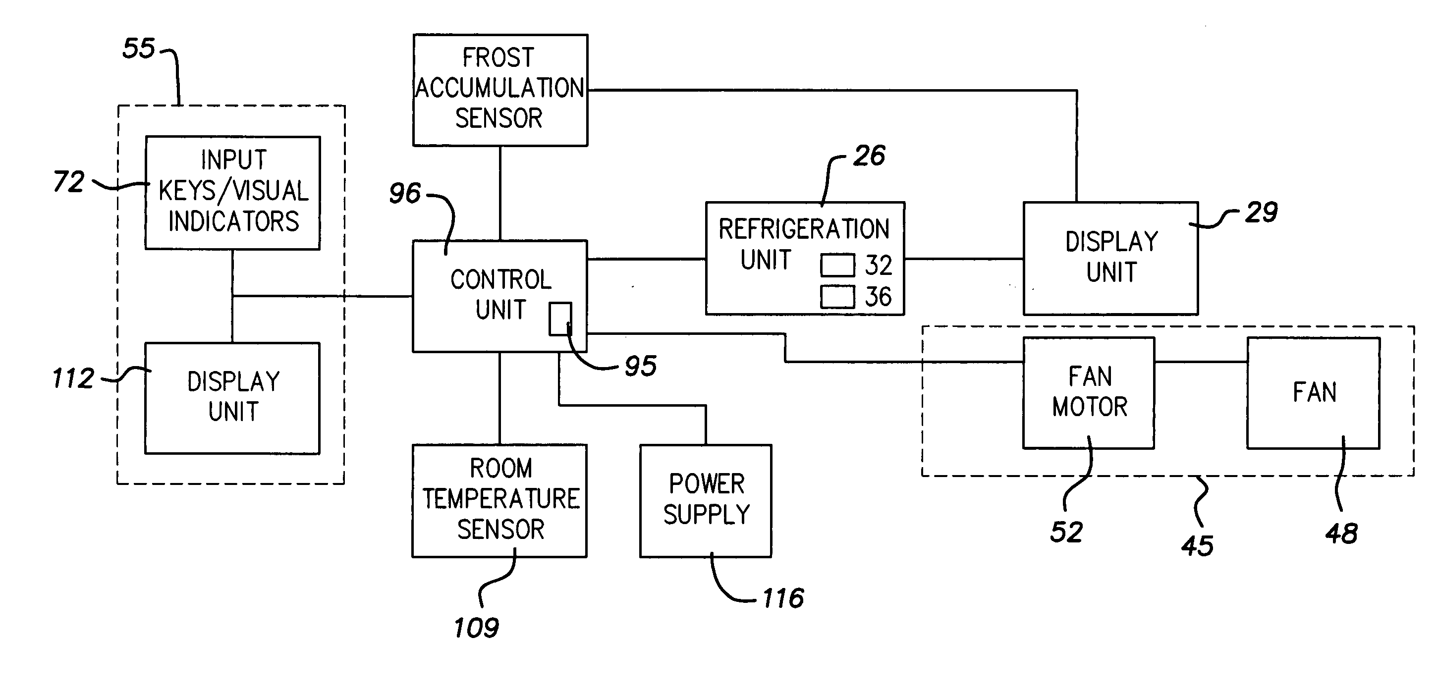
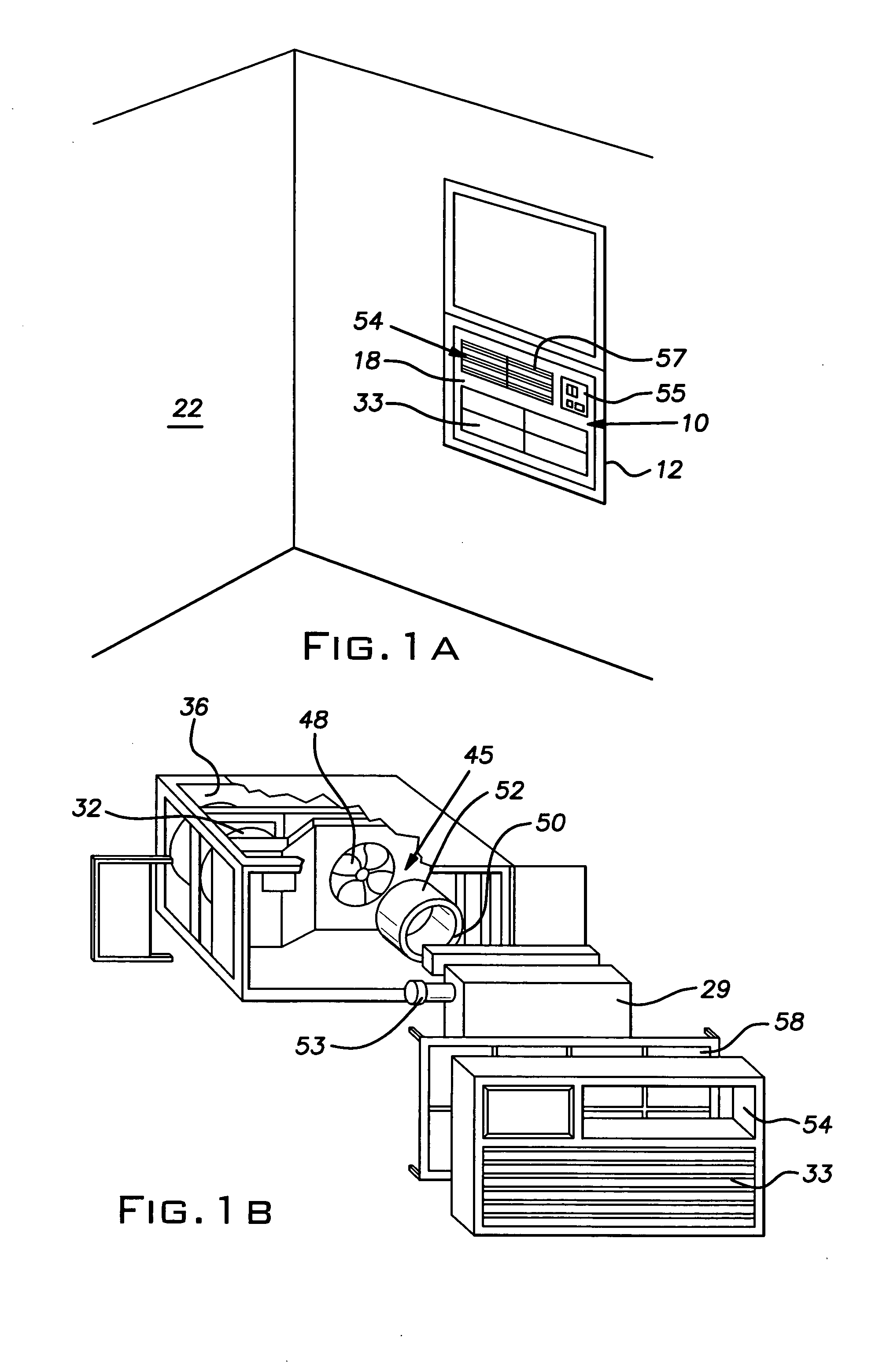
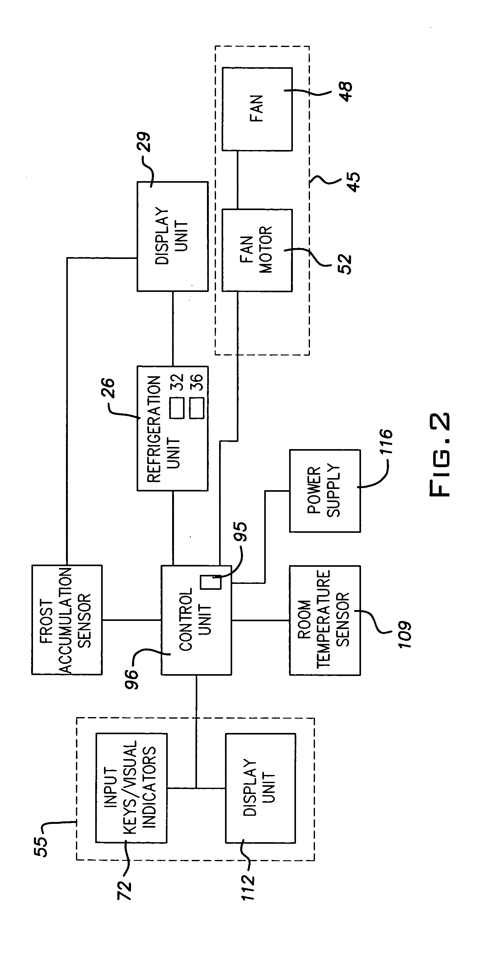
[0030]FIG. 1A illustrates a variable speed room air conditioner 10 disposed in a window frame 12 in a manner known in the art. Although depicted in a window frame 12 in FIG. 1A, the air conditioner 10 can be adapted for installation in any aperture formed in an external wall of an enclosed structure such as a house, garage, storage unit, school and office building. An interior face 18 of the air conditioner 10 projects into a room 22 from the window frame 12 while a fresh air inlet (not shown) projects externally from the window frame 12 in a position to draw fresh air from an external environment. With the...


PUM


Abstract

A variable speed air handling system for cooling and / or heating a room and a method of controlling the system. The system includes a fan assembly to transport air from the system into the room, the fan assembly having a substantially continuously adjustable speed within a range of speeds defined by a predetermined upper limit and a predetermined lower limit. A user interface transmits a signal in response to a desired speed of the fan assembly input by an operator via the user interface. The system further includes a control unit to substantially continuously adjust the speed of the fan assembly to a speed in the range of speeds in response to the signal transmitted by the user interface, and a climate control unit for heating and / or cooling the air to be transported from the air conditioner by the fan assembly.

Description

BACKGROUND OF THE INVENTION [0001] The present invention relates generally to air handling systems, and more particularly to air conditioners that are variably adjustable over a range of operating speeds to blow air at desired rates. [0002] Conventional air conditioners include a refrigeration unit, a motor driven fan to direct air over a heat exchanger cooled by the refrigeration unit, intake and exhaust ports, and a control portion to allow an operator to select a predetermined operational speed of the fan. The air conditioner is controlled according to a relationship between a desired temperature setting input via the control portion, and a temperature of the room to be cooled as sensed by a thermistor. When the sensed temperature exceeds the desired temperature by a predetermined value, the refrigeration unit is activated to cool the heat exchanger which, in turn, cools air being directed over the heat exchanger by the fan. The refrigeration unit is deactivated when the sensed t...

Claims


Application Information

Patent Timeline
IPC IPC(8): F24F1/02F24F11/00F24F13/22
CPCF24F1/027F24F11/001F24F11/0012F24F11/0079Y02B30/746F24F2011/0054F24F2011/0065F24F2011/0068F24F2011/0072F24F13/22F24F11/30F24F2110/00F24F2110/10F24F2140/30F24F11/66F24F11/56F24F11/59F24F11/77Y02B30/70
Inventor VIOLAND, GARYFASOLO, PAUL
Owner ELECTROLUX HOME PROD CORP NV
Why Eureka
Eureka Blog
Learn More