
Information processor, TV system, control method and program

a technology of information processor and control method, applied in the field of information processor, can solve the problems of increasing the cost of sub-information processor with improvement in the function of the receiver, increasing the total installation cost, and increasing the cost of the total installation cost. , to achieve the effect of preventing confusion of users of sub-information processor, low cost and smooth operation of effectively using limited video resources

Inactive Publication Date: 2005-05-26
CANON KK
View PDF14 Cites 91 Cited by
  • Summary
  • Abstract
  • Description
  • Claims
  • Application Information

AI Technical Summary

Benefits of technology

[0068] According to the first invention according to this application, the digital broadcast can be viewed using a device called a legacy device such as an analog TV and an analog VTR. This enables the digital broadcast to be viewed at a low cost.
[0069] Furthermore, according to the second invention according to this application, there is no possibility of sudden switching of video data being processed by the sub-information processor even if the video source of video data being output to the sub-information coincides with the video source to be used.
[0070] Furthermore, according to the third invention according to this application, confusion of users of sub-information processors can be prevented by mediation based on resource maintenance information even if requests for output of video data included in a same video source is made on the video source from

Problems solved by technology

However, such tendency for digitization of the display is innovative as to functions and applications of the display, but its cost increases with improvement in function of the receiver.
This is one of causes of the fact that spread of digital TV stagnates at present.
Furthermore, there arises no particular problem if a high-functional receiver is installed on a one-per-household basis, but if consumers install digital TV not on “one-per-household basis” but on “one-per-room basis” as in the case of conventional analog TV, a total installation cost significantly increases.
Therefore, it is difficult to use digital TV directly as a replacement for analog TV at present.
Further, if digital TV comes into use, there arises a possibility that analog TV or the like that has been used becomes unnecessary, and thus money spent for purchase of analog TV goes to waste.
Therefore, the large TV receiver set which is shared by family members is often hard to be monopolized by some of the members.
Further, if when several persons use a large TV receiver set having a multi view display function as described above, some of them display on a sub view a program other than a program displayed on a main view, the main view decreases in size, and thus others may be annoyed.
However, if a video source output from the external output terminal of the large TV receiver set during recording is changed, recording of video contents selected may end in failure, thus making it impossible to view the video contents.
Accordingly, for using an analog device such as a conventional analog TV as the child device, expensive functions such as a demultiplexer for taking desired MPEG 2 data from a TS packet, an MPEG 2 video decoder for expansion and an audio video decoder are required.
This contradicts the purpose of viewing the digital broadcast at a low cost while using a conventional analog device.
This increases the cost of the parent device.
Furthermore, if a program or the like being transmitted from the parent device to the child device is freely changed by the parent device, the picture may be switched unexpectedly so that a desired picture is missed on the child device side.
This causes shortage of tuners, resulting in competition of video resources.
H8-79720, there arises a problem similar to competition for the tuner between video resources if a plurality of users try to. regenerate the picture from a storage device such as a memory.
In particular, if wireless LAN is involved, child devices, and the child device and the parent device are often at a distance from each other, and therefore a situation may not understood quickly, resulting in significant confusion on operations.
If a required number of tuners different in type are simply provided, competition of video resources can be avoided, but the cost considerably increases, and it is thus impractical.
Further, in the conventional parent device / child device TV system disclosed in Japanese Patent Application Laid-Open No. 2000-181421, a program cannot be selected from the child device to the parent device.
Furthermore, if a program or the like being transmitted from the parent device to the child device is freely changed by the parent device, the picture may be switched unexpectedly so that a desired picture is missed on the child device side, or recording ends in failure on the child device side.

Method used


Image

  • Information processor, TV system, control method and program
  • Information processor, TV system, control method and program
  • Information processor, TV system, control method and program

Examples


first embodiment

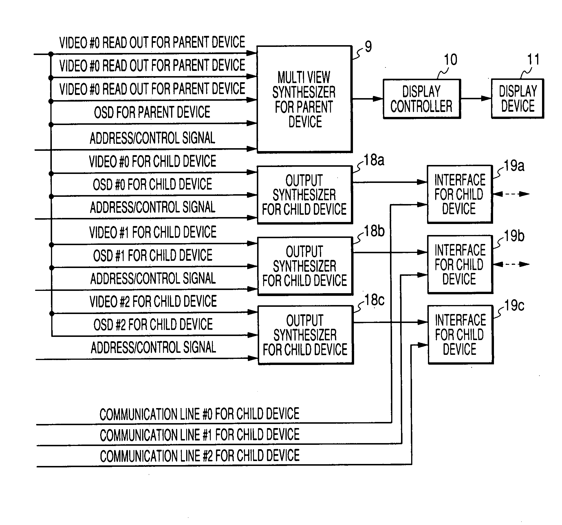
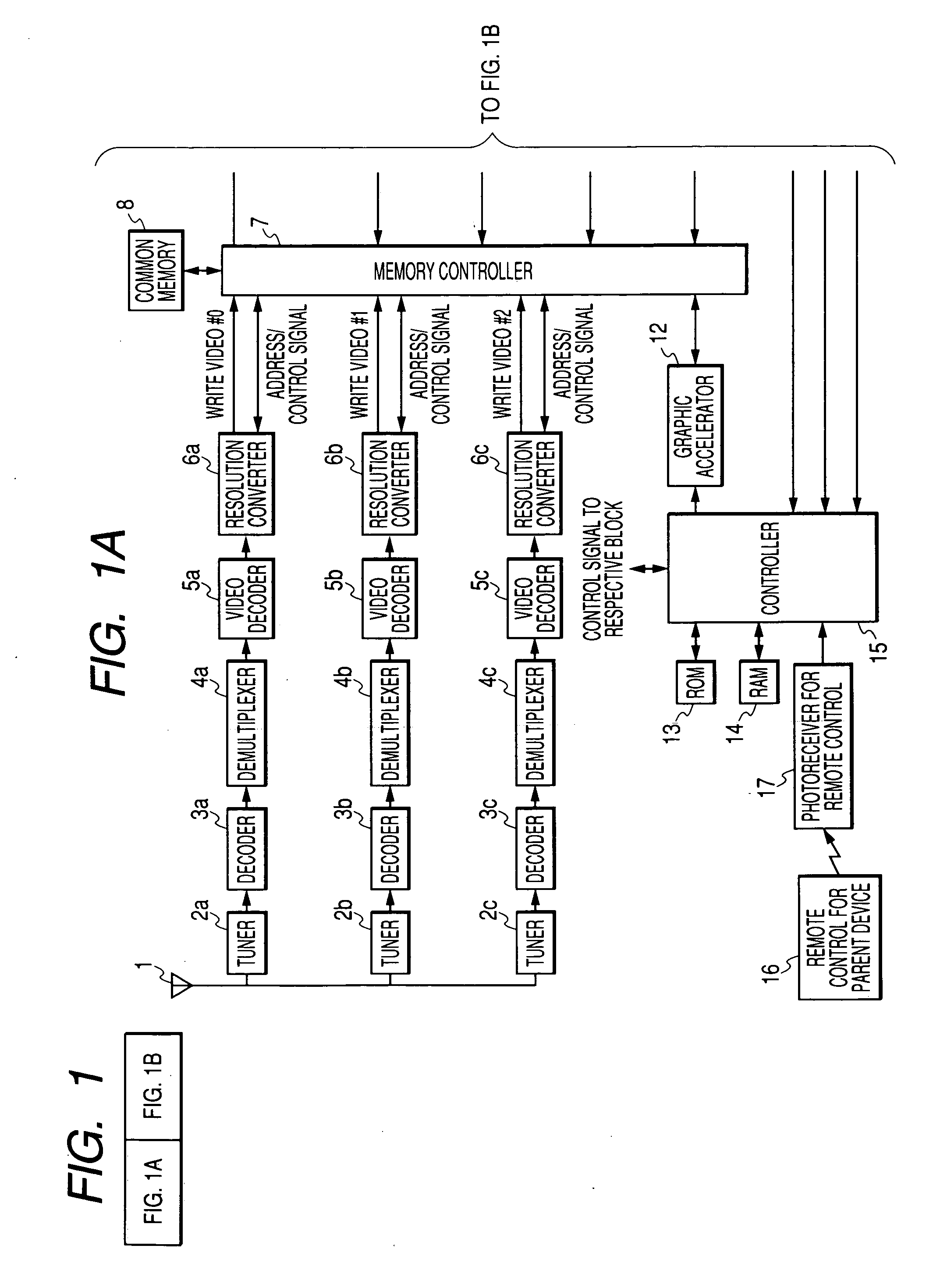
[0152] First, the first embodiment of the present invention will be described. FIGS. 1A and 1B are block diagrams showing the configuration of a parent device having a multi view function constituting a TV system according to the first embodiment of the present invention. The parent device of the first embodiment is configured to enable multi view synthesis display of three independent broadcast video sources on one display based on a predetermined layout. The number of video sources may be 1, 2, 4 or more.

[0153] The parent device of the first embodiment is provided with an antenna 1 such as a parabola antenna. Radio waves of the BS digital broadcast, the CS digital broadcast and the like are received by the antenna 1. In addition to such satellite broadcasts, broadcasts capable of receiving signals from ground waves, optical cables and the like are acceptable. Three tuners 2a, 2b and 2c are connected to the antenna 1. For the tuners 2a to 2c, BS dedicated tuners, CS dedicated tune...

second embodiment

[0229] The second embodiment of the present invention will now be described. In the configuration of the first embodiment, pictures of the same video source are not displayed at the parent device and the child device. However, in the following examples, it is required to display pictures of the same video source at the parent device and the child device at the same time. The examples include cases where (1) one wants to monitor on the parent device side the contents of a program viewed at the child device, (2) in PUSH-type transferring to the child device, pictures on the main view of the parent device are requested to be transferred to the child device, but one wants to continuously view the same pictures at the parent device, (3) in PULL-type transferring to the child device, the parent device is requested to transfer pictures to the child device, but transferring is refused because parent device displays the requested pictures on the main view, and the like.

[0230] The second emb...

third embodiment

[0249] The third embodiment of the present invention will now be described. The first and second embodiments relate mainly to control until pictures are transferred to the child device, while the third embodiment relates mainly to control of the parent device during transferring of pictures to the child device. FIG. 19 shows the configuration of a TV system according to the third embodiment of the present invention.

[0250] The TV system is provided with a display 31 using a display device such as a PDP or CRT, and a set box (hereinafter abbreviated as STB) 32 being a receiver having also a function to transmit video data. The parent device is constituted by a display 31 (main display) and an STB 32 (information processor).

[0251] Further, a remote control device (hereinafter abbreviated as remote control) 33 for remotely operating the STB 32, a video tape recorder (hereinafter abbreviated as VTR) 34, an analog TV receiver set 35 using a display device such as a small CRT, and a conv...


PUM


Abstract

An information processor enabling a digital broadcast to be viewed at a child device at a low cost, a TV system and a program are provided. Video decoders are corrected to the post-stage of demultiplexers, respectively, and video data of MPEG divided by the demultiplexers is decoded by the video decoders. At this time, the video data of MPEG is converted into a display format of a base band in a raster scan form. A common memory having a capacity equivalent to at least one displayed image, and a memory controller controlling the operation of the common memory are further provided. Three write video data output from resolution converters is stored in the common memory under control by the memory controller.

Description

BACKGROUND OF THE INVENTION [0001] 1. Field of the Invention [0002] The present invention relates to an information processor which is used in, for example, a parent device / child device TV system that has as part of a parent device a digital TV having a multi view display function capable of displaying a plurality of video sources, and can transfer at least one video source to a child device monitor provided outside the parent device, a TV system, a control method and a program. [0003] 2. Related Background Art [0004] With digitization of broadcasts and increase in size of view and improvement in fineness in displays, a display form called multi view display in which various video sources are displayed on one display at a time is expected as one of means for using a display as a “window of information in a household”. Some of current.displays have incorporated therein a function capable of receiving broadcasts of 2 channels at a time and displaying the same on a screen at a time, an...

Claims


Application Information

Patent Timeline
IPC IPC(8): H04N7/16
CPCH04N7/163H04N21/4122H04N21/4135H04N21/4181H04N21/42204H04N21/4263H04N21/4751H04N21/434H04N21/43615H04N21/43632H04N21/43637H04N21/4438H04N21/4532H04N21/4331
Inventor YUI, HIDEAKIUEHARA, MAKOTOTSUNODA, TAKASHIONO, KENICHIRONAKANO, MASAKI
Owner CANON KK
Learn More