
Synchronized data transfer system

Active Publication Date: 2005-05-26
INTERACTIVE CONTENT ENGINES LLC
View PDF45 Cites 231 Cited by
  • Summary
  • Abstract
  • Description
  • Claims
  • Application Information

AI Technical Summary

Benefits of technology

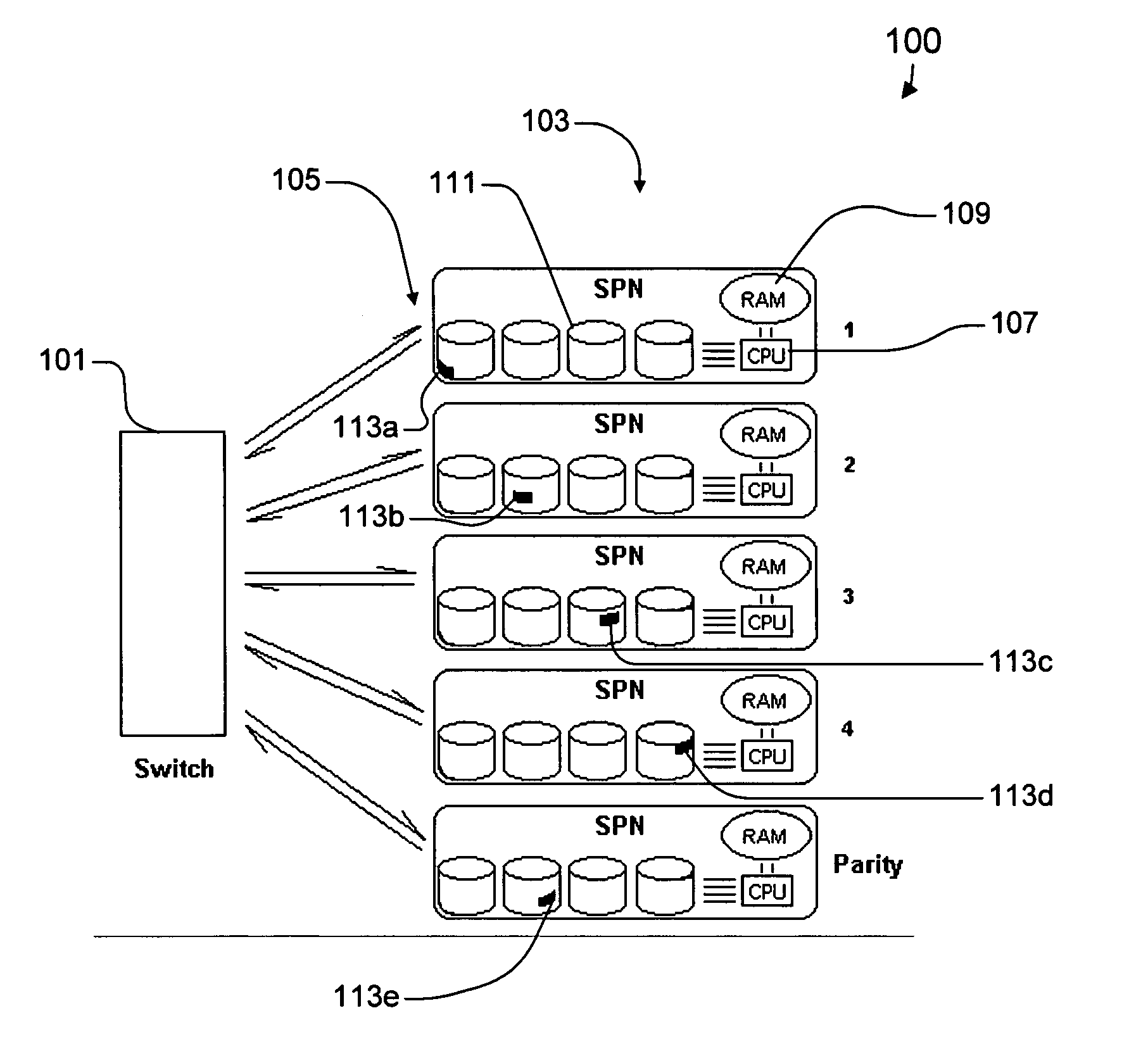
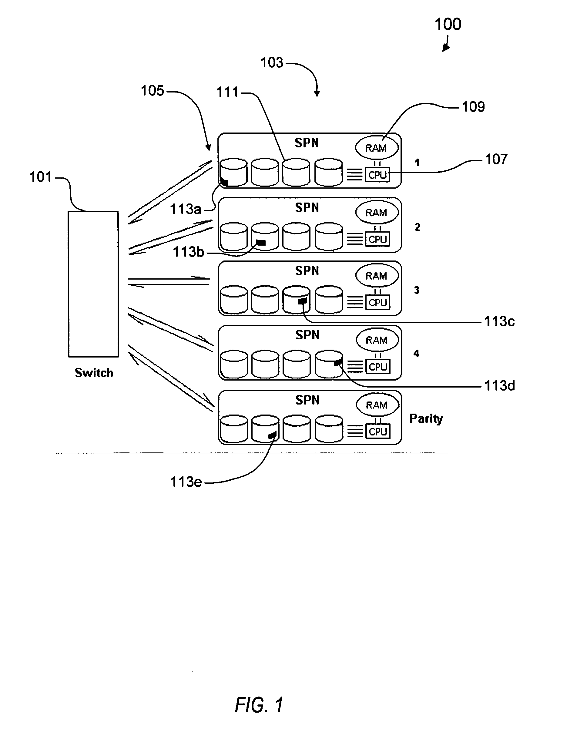
[0013] The architecture described herein accommodates individual components of varying capability to avoid an installation being limited to the point in time when the initial system purchase was made. The use of commodity components guarantees recent well proven technology, avoidance of sole sources, and the lowest cost per stream. Individual component failures are tolerated. In many cases, there is no noticeable change in behavior from a user's perspective. In other cases, there is a brief “self repair” cycle. In many cases, multiple failures may be tolerated. Also, in most if not all cases, the system can recover without requiring immediate attention, making it ideal for “lights out” operation.

Problems solved by technology

The total bandwidth available is limited by the largest available backplane switch.
In other words, there are random amounts of data with random time delays.
The downside is the disk, which, as the sole mechanical device in the design, can only access and transfer data so fast.
This is better, but there are still several problems.
The disk drives, CPU, and memory are each single points of failure that could be catastrophic.
Even with many units, there is a problem with the distribution of titles.
All of a machine's bandwidth cannot be consumed by one title, as it would block access to less popular titles stored only on that machine.
In short, if a user wanted to see an old movie, that user might be out of luck—even though it is loaded in the system.
If the system were based on the standard Local Area Network (LAN) used in data processing, there would be other inefficiencies.
Modern Ethernet-based TCP / IP systems are a marvel of guaranteed delivery, but include a time price caused by packet collisions and re-transmits of partially lost packets and the management needed to make it all work.
There is no guarantee that a timely set of content streams will be available.
Also, each user consumes a switch port and each content server consumes a switch port.
Thus, the switch port count has to be twice the server count, limiting the total online bandwidth.

Method used


Image

  • Synchronized data transfer system
  • Synchronized data transfer system
  • Synchronized data transfer system

Examples


Embodiment Construction

[0012] The following description is presented to enable one of ordinary skill in the art to make and use the present invention as provided within the context of a particular application and its requirements. Various modifications to the preferred embodiment will, however, be apparent to one skilled in the art, and the general principles defined herein may be applied to other embodiments. Therefore, the present invention is not intended to be limited to the particular embodiments shown and described herein, but is to be accorded the widest scope consistent with the principles and novel features herein disclosed.

[0013] The architecture described herein accommodates individual components of varying capability to avoid an installation being limited to the point in time when the initial system purchase was made. The use of commodity components guarantees recent well proven technology, avoidance of sole sources, and the lowest cost per stream. Individual component failures are tolerated....


PUM


Abstract

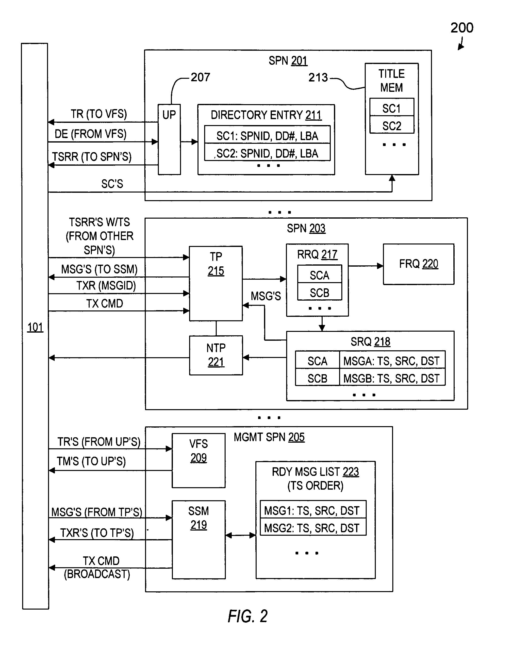
A synchronized data transfer system including storage processor nodes, a backbone communication switch, multiple titles subdivided into subchunks and distributed across the nodes, a user process executed on a first node, a transfer process executed on a second node, and a management process executed on a management node. The user process sends a timestamped read request to request a corresponding subchunk. The transfer process sends a message to the management process for each received read request, where each message identifies source and destination nodes. The management process broadcasts transmit commands to initiate sequential transmit periods, receives the messages, and selects from among the received messages to ensure that each node sends or receives only one subchunk during each transmit period. The management process sends a transmit request for each selected message, and the transfer process sends a subchunk identified by a transmit request in response to the transmit command.

Description

CROSS-REFERENCE TO RELATED APPLICATIONS [0001] This application claims the benefit of U.S. Provisional Application No. 60 / 526,437 filed on Dec. 2, 2003, and is a continuation-in-part of U.S. patent application entitled “Interactive Broadband Server System” Ser. No. 10 / 304,378 filed Nov. 26, 2002, pending, which itself claims the benefit of U.S. Provisional Application No. 60 / 333,856 filed on Nov. 28, 2001, all of which having a common inventor, being commonly assigned, and being herein incorporated by reference for all intents and purposes.BACKGROUND OF THE INVENTION [0002] 1. Field of the Invention [0003] The present invention relates to interactive broadband server systems, and more particularly, to an interactive content engine that employs a synchronized data transfer system to facilitate delivering multiple simultaneous isochronous data streams at high speed. [0004] 2. Description of the Related Art [0005] It is desired to provide a solution for the storage and delivery of stre...

Claims


Application Information

Patent Timeline
IPC IPC(8): H04LH04L29/06H04L29/08H04N5/00H04N7/173
CPCH04L29/06H04L29/06027H04L2029/06054H04N7/17318H04N21/2182H04N21/21825H04L67/1002H04N21/2318H04N21/2326H04N21/2405H04L65/4084H04L67/1097H04L67/325H04N21/2315H04L67/10015H04L65/612H04L67/1001H04L67/62H04L9/40H04L65/1101
Inventor ROSE, STEVEN W.
Owner INTERACTIVE CONTENT ENGINES LLC
Learn More