
Electronically-controlled suspension apparatus and damping force control method

a technology of suspension apparatus and control method, which is applied in the direction of bicycle equipment, instruments, transportation and packaging, etc., can solve the problems of reducing the durability of inner components of the damper, affecting the ride comfort of the vehicle, and affecting the performance of the damper, so as to prevent a full extension or a full bumping, prevent inner components from being damaged, and harden the damping force characteristics of the damper

Inactive Publication Date: 2005-05-26
HL MANDO CORP
View PDF26 Cites 27 Cited by
  • Summary
  • Abstract
  • Description
  • Claims
  • Application Information

AI Technical Summary

Benefits of technology

[0013] It is, therefore, an object of the present invention to provide an electronically-controlled suspension apparatus and damping force control method which hardens damping force characteristics of a damper when a stroke of the damper (or a relative displacement of a vehicle body with respect to a wheel axle) is in a critical stroke range, thus preventing a full extension or a full bumping from occurring in the damper, thereby preventing inner components of the damper from being damaged and enhancing the riding comfort of a vehicle.

Problems solved by technology

However, in the case where the sky-hook damper theory is adapted to enhance the riding comfort of the vehicle and the damper having damping force characteristics softer than those of a general damper for normal operation of the vehicle is mounted to the vehicle, when the vehicle runs over the protrusion or a pothole of the road, the full extension or the full bumping may occur.
In this case, the riding comfort of the vehicle is deteriorated and the durability of inner components of the damper is reduced.
Particularly, when the stop rubber installed in the inside of the damper is damaged by impacts made thereon due to the full extension, foreign matters, such as rubber particles, may be generated in the inside of the damper.
In addition, if the undesirable material is lodged into an orifice of the actuating unit for adjusting the damping force characteristics of the damper, incorrect operation or failure of the damper may occur.
However, the stroke response damper is disadvantageous in that the damping force thereof varies discontinuously and abruptly deteriorating the driving comfort of the vehicle.

Method used


Image

  • Electronically-controlled suspension apparatus and damping force control method
  • Electronically-controlled suspension apparatus and damping force control method
  • Electronically-controlled suspension apparatus and damping force control method

Examples


Embodiment Construction

[0022] Hereinafter, embodiments of the present invention will be described in detail with reference to the attached drawings. Further, it should be noted that the following description of the embodiments of the present invention will be focused on only one set of a wheel and a damper for simplicity even though four sets thereof are mounted to a vehicle.

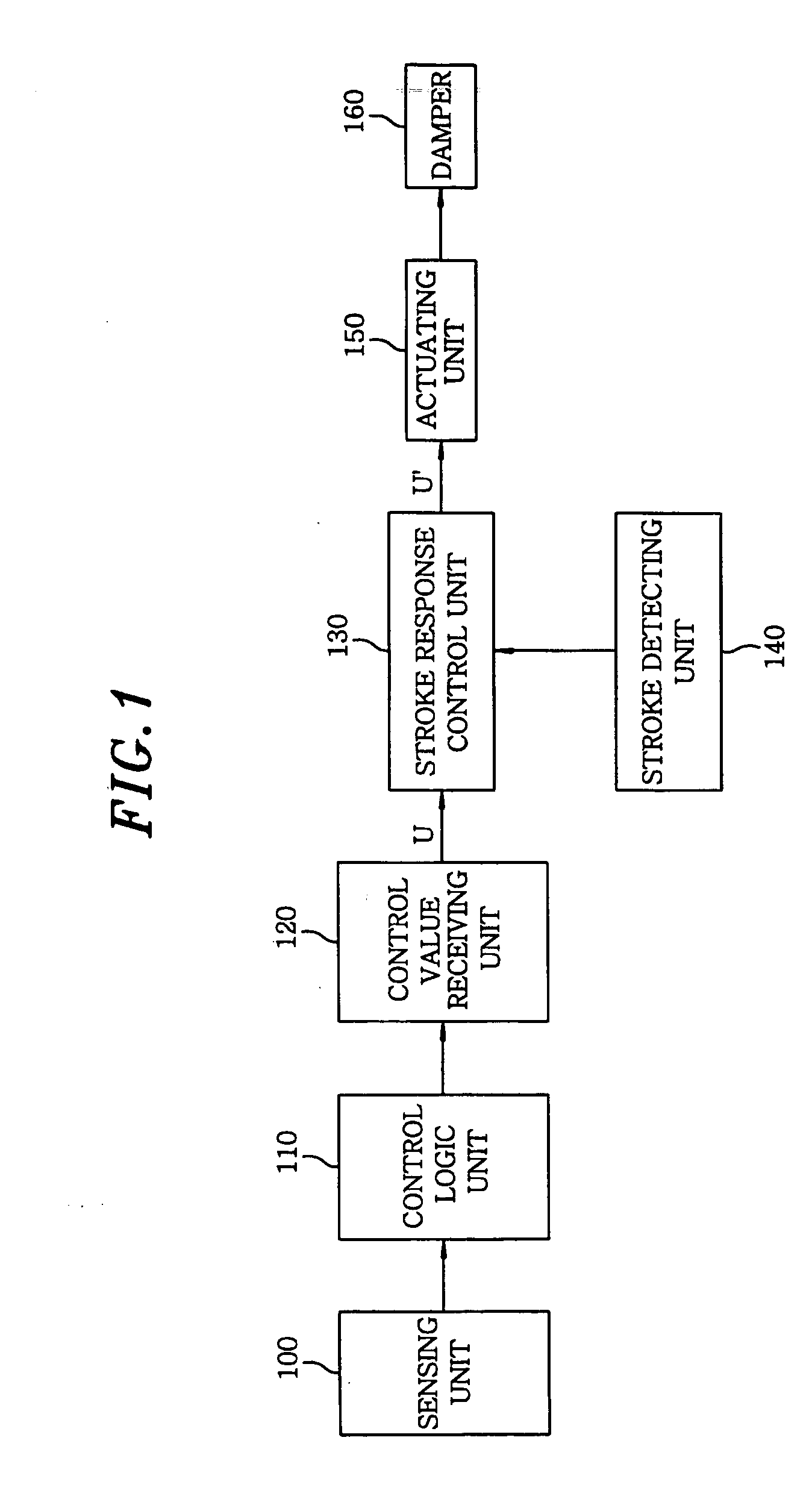
[0023]FIG. 1 is a block diagram of an electronically-controlled suspension apparatus in accordance with a preferred embodiment of the present invention. As shown in FIG. 1, the electronically-controlled suspension apparatus of the present invention includes a sensing unit 100, a control logic unit 110, a control value receiving unit 120, a stroke response control unit 130, a damper 160 installed between a vehicle body and a wheel axle, an actuating unit 150 for controlling damping force characteristics of the damper 160 and a stroke detecting unit 140 for detecting a stroke of the damper 160.

[0024] The sensing unit 100 includes a fi...


PUM


Abstract

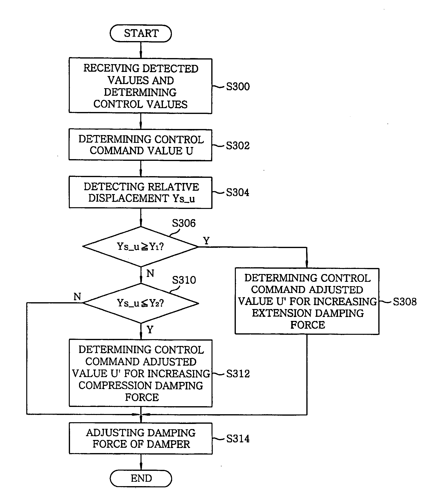
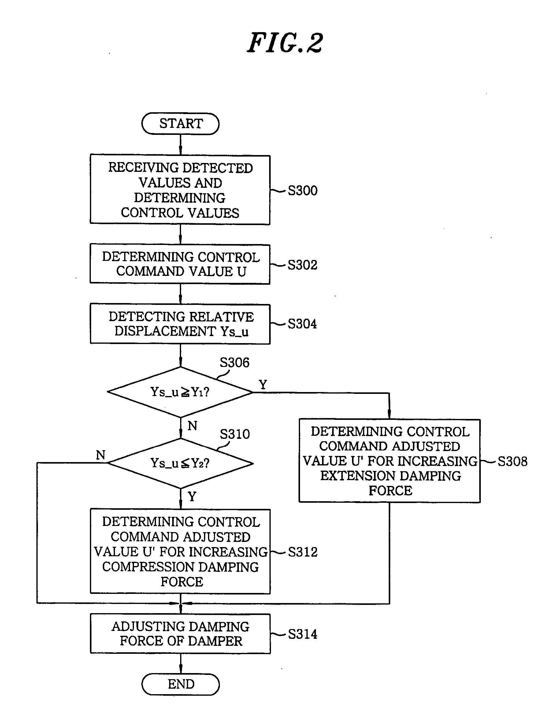
An electronically-controlled suspension apparatus includes a stroke detecting unit for detecting a relative displacement of the vehicle body with respect to the wheel axle; a stroke response control unit for determining a control command adjusted valve; and an actuating unit which is operated according to the control command adjusted value, thus adjusting the extension or compression damping force of the damper. The stroke response control unit determines the control command adjusted value for increasing an extension or compression damping force of the damper when the relative displacement is equal to or greater than a first predetermined value, or is less than or equal to a second predetermined value.

Description

FIELD OF THE INVENTION [0001] The present invention relates to an electronically-controlled suspension apparatus; and, more particularly, to an electronically-controlled suspension apparatus and damping force control method, which is capable of preventing a full extension or a full bumping of a damper by changing damping force characteristics of the damper when a stroke of the damper is within a critical stroke range. BACKGROUND OF THE INVENTION [0002] In general, a suspension apparatus connects a wheel axle to a vehicle body to prevent vibrations and impacts transmitted from vehicle wheels from being directly transmitted to the vehicle body, so that it can prevent a vehicle body and goods contained therein from being damaged and improve riding comfort of a vehicle. Also, the suspension apparatus transfers to the vehicle body either a driving force generated from driving wheels or brake force of individual wheels when braking the vehicle to a stop, endures a centrifugal force genera...

Claims


Application Information

Patent Timeline
IPC IPC(8): B60G17/018B60G17/015B60G17/06G06F7/00
CPCB60G17/018B60G17/06B60G2500/104B60G2500/10B60G2400/252B60G17/015
Inventor KIM, WANIL
Owner HL MANDO CORP
Learn More