
Implantable heart assist devices and methods

Inactive Publication Date: 2005-05-26
PAUL A SPENCE
View PDF46 Cites 17 Cited by
  • Summary
  • Abstract
  • Description
  • Claims
  • Application Information

AI Technical Summary

Benefits of technology

[0014] The present invention is generally directed toward heart support and assist devices including fully passive restraints, combinations of passive and active devices and fully active devices for assisting with heart contractions. Passive restraints generally include an external support member, which may be a strap, web or mesh, sheathing or other member configured to extend around the outside of the heart coupled with an internal support member extending within at least one of the ventricles and against one side of the interventricular septum. This type of passive restraining system can assist the heart muscle by supporting those portions of the muscle necessary to produce efficient contractions either naturally or with another active assist device. This support is provided in a manner that minimizes trauma to the heart muscle. Additional internal tensile members, such as cables, may be connected to the external tensile member or members longitudinally and / or transversely through one or both ventricles. These cables will assist with long axis and short axis shortening of the heart muscle during each contraction.
[0015] Combinations of passive and active devices may include, for example, external support members, in the form of straps, sheaths, wraps, mesh elements or webs, etc., combined with a blood pump connected for fluid communication directly with the left ventricle, right ventricle or both. Alternatively, a fluid inflatable bladder may be placed between the external tensile member and the outside surface of the heart to provide compression to one or both of the ventricles to assist in pumping blood through the heart. Finally, an active contraction device may integrate an external tensile member system with a powered actuator device to provide cyclical compression of the heart muscle through a pulling action on the tensile member or members.
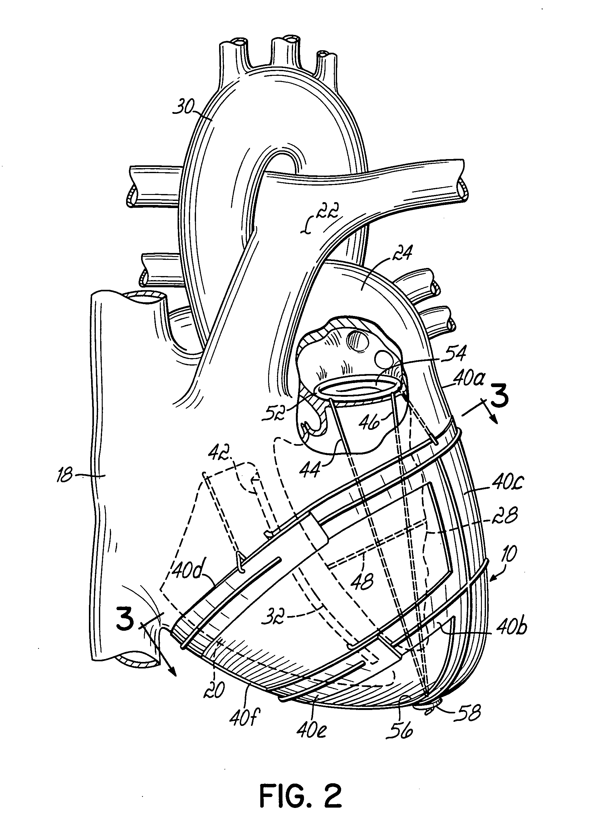
[0019] In accordance with another aspect of the invention, at least one internal tensile member is provided and configured to be connected lengthwise within the left ventricle between the mitral valve of the heart and the apex of the left ventricle. The internal tensile member inhibits lengthening of the ventricle when the powered actuator or actuators pull the tensile members to compress the left and right ventricles. As further options, transverse, internal tensile members may be connected within the left ventricle between the outside wall thereof and the interventricular septum to control widthwise expansion. Also, one or more internal tensile members may be utilized in the right ventricle for similar purposes.
[0020] As additional aspects of the invention, the tensile members may be contained in sleeves to prevent cutting of the heart by the tensile members during use. Also, a plurality of coronary obstruction preventing members may be used between the tensile members and the coronary arteries on the outside of the heart for preventing the coronary arteries from being compressed and obstructed by the tensile members.

Problems solved by technology

The treatment of heart failure over the long term is a difficult problem.
At the same time, weak cardiac muscle function is becoming an increasing problem.
Patients are surviving longer and more patients are surviving myocardial infarcts leading to a large pool of patients who are inadequately served by current medical practice.
Drug treatment to increase the strength of mycardial contraction has been unsuccessful over the long term.
Recently, biventricular pacing (rather than the usual univentricular pacing) has been tried and this offers some promise in selected patients but is unlikely to solve the problem.
Conventional methods have been unable to inject adequate energy into the cardiovascular system.
Past attempts with the Jarvic heart or other replacement systems have met with problems such as failure due to thromboembolism.
These clots eventually break off and lodge in the brain leading to strokes or resulting in ischemic injury to other body organs.
It has also been postulated that long-term exposure of blood to large artificial surfaces sets up a chronic inflammatory reaction which may predispose the patient to infection.
This device requires considerable residual cardiac function to operate.
Blood clotting, hemolysis and degradation of blood become problems in this situation.
Pneumatically and electrically driven devices have been evaluated, but these devices have not reached clinical application.
Unfortunately, this does not mimic the way the heart contracts.
The drawback to this device, however, is that the interventricular wall or septum experiences significant trauma due to the surgical implantation of the band within the wall or septum itself.
Especially in cases in which the interventricular wall is already weakened, such trauma could severely damage the heart.
This system, however, squeezes the entire heart muscle at one time and will tend to cause weaker portions of the heart to bulge outward while stronger portions of the heart muscle retain a normal shape.
Unfortunately, this device will also tend to cause weakened portions of the heart muscle to bulge around the left ventricle rather than causing the intended function of expelling blood from the ventricle.
Thus, the ejection fraction of blood can be deficient with this device as well.
Despite the intuitively attractive nature of heart assist devices, no device has ever been clinically proven.
It is not surprising that merely squeezing the left and right ventricles with a device wrapped around both ventricles has not been successful.
There is also limited short axis shortening because the device does not squeeze the left ventricle in isolation, but with the right ventricle.

Method used


Image

  • Implantable heart assist devices and methods
  • Implantable heart assist devices and methods
  • Implantable heart assist devices and methods

Examples


Embodiment Construction

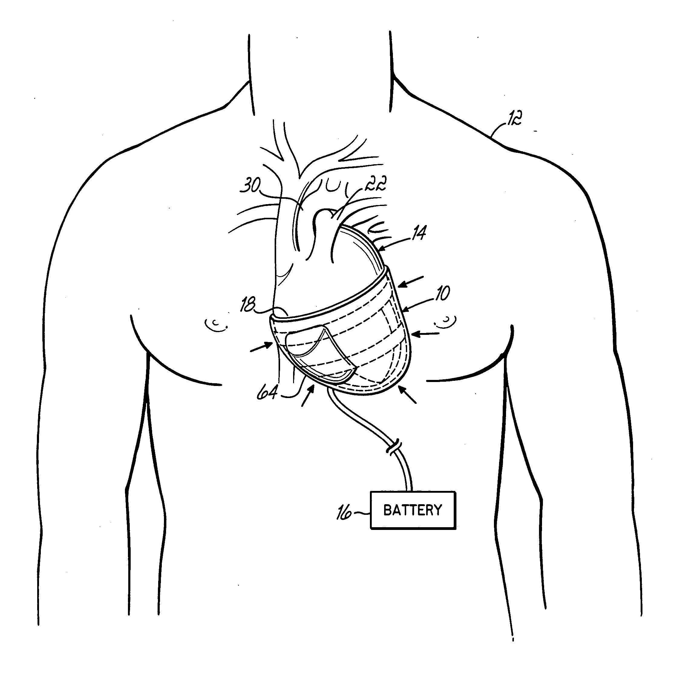
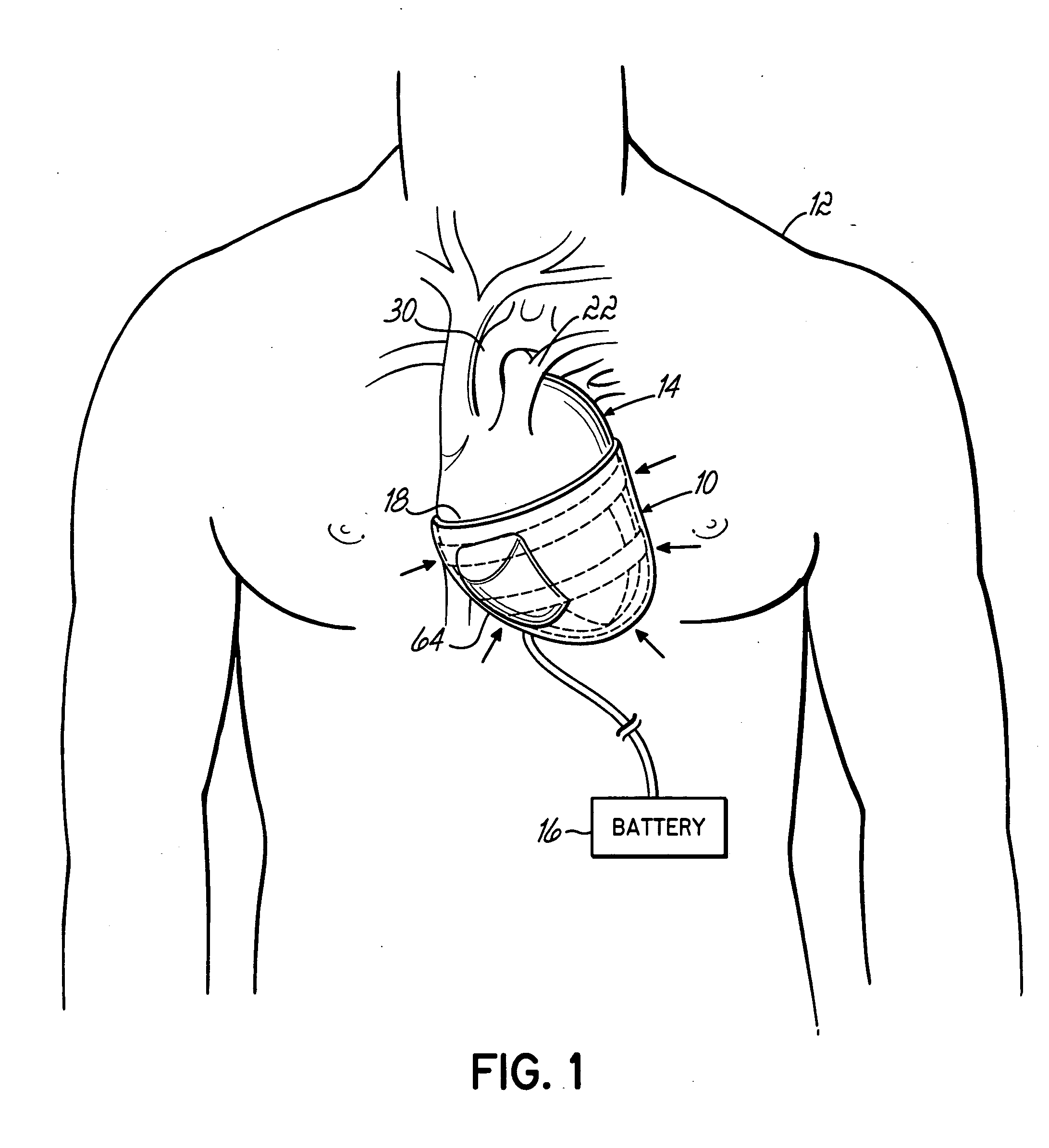
[0048]FIG. 1 illustrates a heart assist device 10 constructed in accordance with the invention and schematically illustrated implanted within a patient 12 in surrounding relation to the patient's heart 14. A power supply 16, such as an electric or pneumatic power supply, is operatively connected to heart assist device 10 for reasons to be discussed below. As generally shown in FIG. 2, heart 14 has four chambers. The right atrium 18 receives blood flowing through veins in the patient's body. The right ventricle 20 pumps the blood to the lungs of the patient through the pulmonary artery 22. The left atrium 24 receives oxygenated blood flowing back from the patient's lungs through the pulmonary vein and the left ventricle 28 pumps this blood out through the aorta 30 to the patient's body. The right and left ventricles 20, 28 compress simultaneously during this pumping action and, in a normal heart, anywhere between about 50% and 80% of the blood in these chambers will be expelled as de...


PUM


Abstract

Heart support and assist devices for supporting and assisting the pumping action of the heart. Various embodiments include mesh support devices, devices using straps, spiral-shaped devices, catheter-based devices and related methods.

Description

[0001] This application is a divisional of application Ser. No. 09 / 677,981 filed Oct. 3, 2000 (now pending), the disclosure of which is fully incorporated herein by reference.FIELD OF THE INVENTION [0002] The present invention generally relates to devices used to physically support the heart and, alternatively, also actively assist the pumping action of the heart. BACKGROUND OF THE INVENTION [0003] The treatment of heart failure over the long term is a difficult problem. At the same time, weak cardiac muscle function is becoming an increasing problem. Patients are surviving longer and more patients are surviving myocardial infarcts leading to a large pool of patients who are inadequately served by current medical practice. Drug treatment to increase the strength of mycardial contraction has been unsuccessful over the long term. Recently, biventricular pacing (rather than the usual univentricular pacing) has been tried and this offers some promise in selected patients but is unlikely...

Claims


Application Information

Patent Timeline
IPC IPC(8): A61B17/00A61F2/00A61M1/10
CPCA61B17/00234A61B2017/00243A61M1/1068A61F2/2487A61M1/106A61F2/2481A61M60/894A61M60/289A61M60/187A61M60/481A61M60/191A61M60/468
Inventor ORTIZ, MARKSPENCE, PAUL A.
Owner PAUL A SPENCE
Learn More