
Electrical connector apparatus

a technology of electrical connectors and apparatuses, applied in the direction of coupling device details, coupling device connections, coupling/disassembly parts, etc., can solve the problems of limited cleaning effect and inability to make plugging at a given angle, and achieve the effect of improving cleaning

Inactive Publication Date: 2005-05-26
HIROSE ELECTRIC GROUP
View PDF5 Cites 10 Cited by
  • Summary
  • Abstract
  • Description
  • Claims
  • Application Information

AI Technical Summary

Benefits of technology

The invention provides an electrical connector apparatus with a small storage space for the metal shutter, capable of plugging at a given angle and improving cleaning effect. The first and second electrical connectors are designed to bring the contact elements into contact with each other from the initial plugging stage to the complete plugging stage, thereby minimizing the storage space for the metal shutter. The metal shutter is turned to the retreated position so that there is no need for a large storage space, permitting miniaturization of the apparatus. The invention also allows for plugging at a given angle and minimizes EMI.

Problems solved by technology

In addition, the plugging angle between the first and second lelectrical connectors is determined by the angle of the tapered outer face of the first electrical connector so that it is impossible to make plugging at a given angle.
Moreover, the terminals make contact at the final stage of plugging, providing the limited cleaning effect.

Method used


Image

  • Electrical connector apparatus
  • Electrical connector apparatus
  • Electrical connector apparatus

Examples


Embodiment Construction

[0025] A preferred embodiment of the invention will now be described with reference to the accompanying drawings.

1. Uses

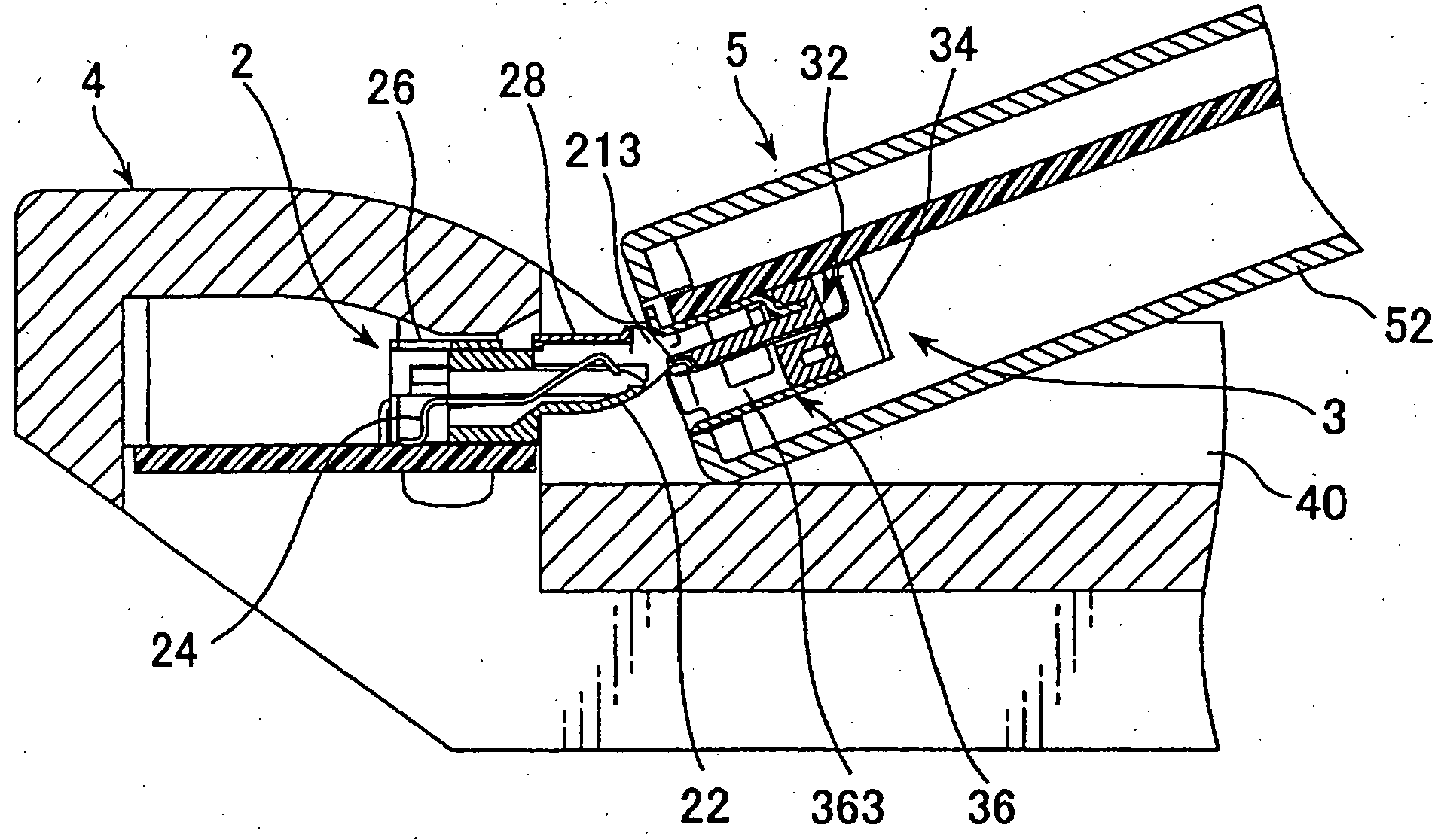
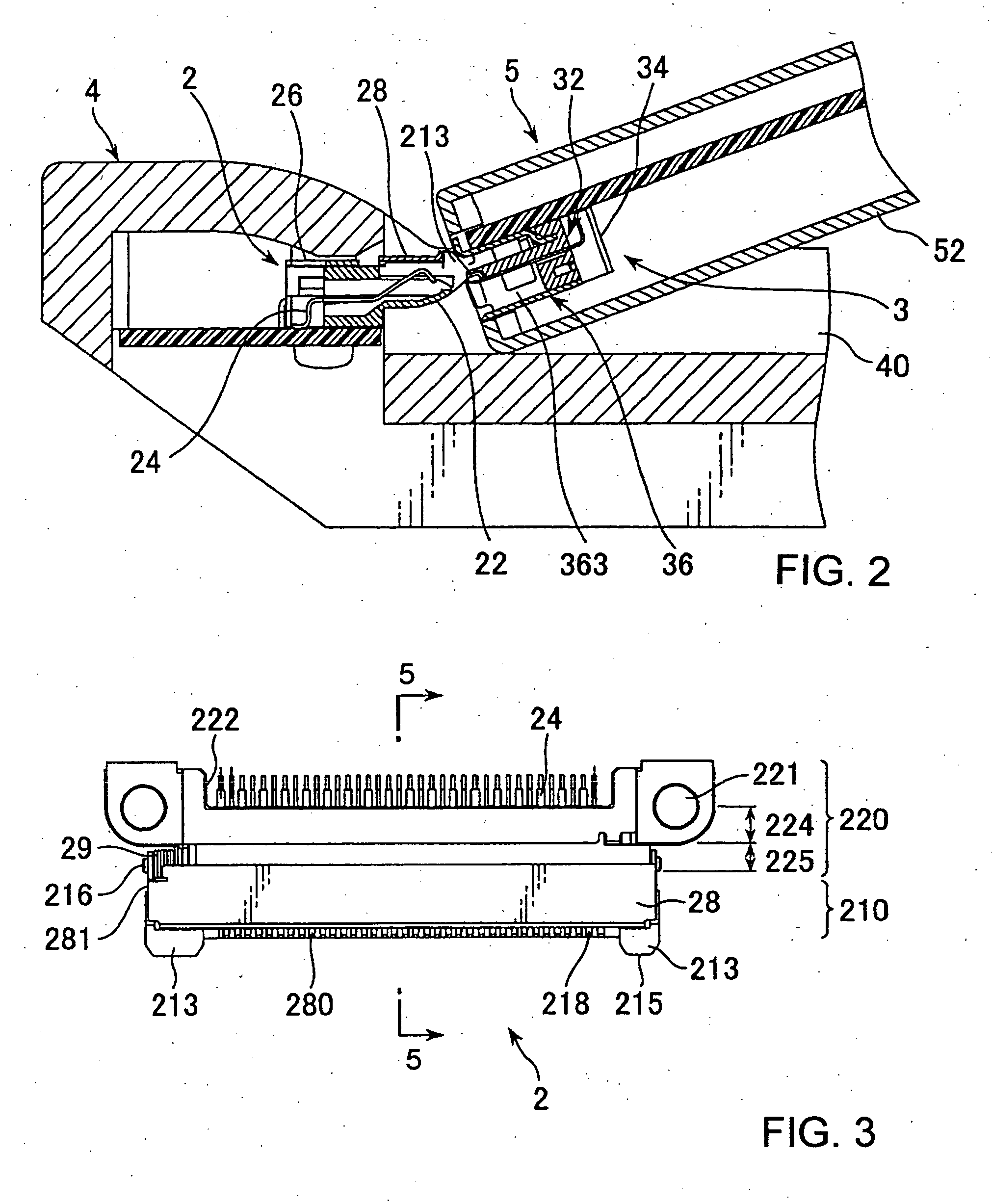
[0026] In FIGS. 1 and 2, an electrical connector system 1 consists of a female connector 2 and a male connector 3. The female connector 2 and the male connector 3 are secured to a cradle 4 and a case 5, respectively. The cradle 4 is made by bending a rectangular resinous plate at right angles along a center line to provide an L-shaped section. It is placed on a table 6, with the central portion upward, for use. The case 5 is made of a rectangular resinous plate. It is movable on the cradle 4 that is at rest. A case receiving section 40 is provided on the bottom 42 of the cradle 4.

[0027] The female connector 2 and the male connector 3 are electrically connected to boards 41 and 51 which are disposed in the cradle 4 and the case 5, respectively. When the case 5 is fully attached to the cradle 4 as shown in FIG. 1, the male connector 3 is plugged to the female con...


PUM


Abstract

An electrical connector apparatus consists of first and second electrical connectors (2, 3). The second electrical connector (3) is inserted into the first electrical connector (2) in an oblique direction and then fully plugged to the first electrical connector (2) by turning the second electrical connector (3). The first electrical connector includes an insulative housing (22), at least one contact element (24) provided in the insulative housing (22), and a metal shutter (28) pivoted to the insulative housing (22) to cover the contact element (24) in the insulative housing (22). The second electrical connector (3) includes a plate member (320) which enters between the metal shutter (28) and the contact element (24) upon plugging.

Description

BACKGROUND OF THE INVENTION [0001] 1. Field of the Invention [0002] The present invention relates to an electrical connector system provided on a portable information device, such as a PDA, and especially to an electrical connector system with an electrical connector being inserted into a mating electrical connector at an angle or in an oblique direction. [0003] 2. Description of the Related Art [0004] JP 2003-168527 discloses a conventional electrical connector system of this type. The electrical connector system consists of first and second electrical connectors. In order to reduce the plugging / unplugging force, the second electrical connector is plugged into the first electrical connector in an oblique direction and then turned to complete the plugging. In order to permit the second electrical connector being inserted into the first electrical connector at an initial plugging stage, the first electrical connector has a tapered outer face extending forwardly. Also, it has a relati...

Claims


Application Information

Patent Timeline
Patent Type & Authority Applications(United States)
IPC IPC(8): H01R13/453H01R13/52
CPCH01R13/453H01R12/73H01R12/88H01R23/7073H01R12/724
Inventor FUNATSU, AKIRA
Owner HIROSE ELECTRIC GROUP
Learn More