Measurement method by OTDR and terminal station apparatus
- Summary
- Abstract
- Description
- Claims
- Application Information
AI Technical Summary
Benefits of technology
Problems solved by technology
Method used
Image
Examples
first embodiment
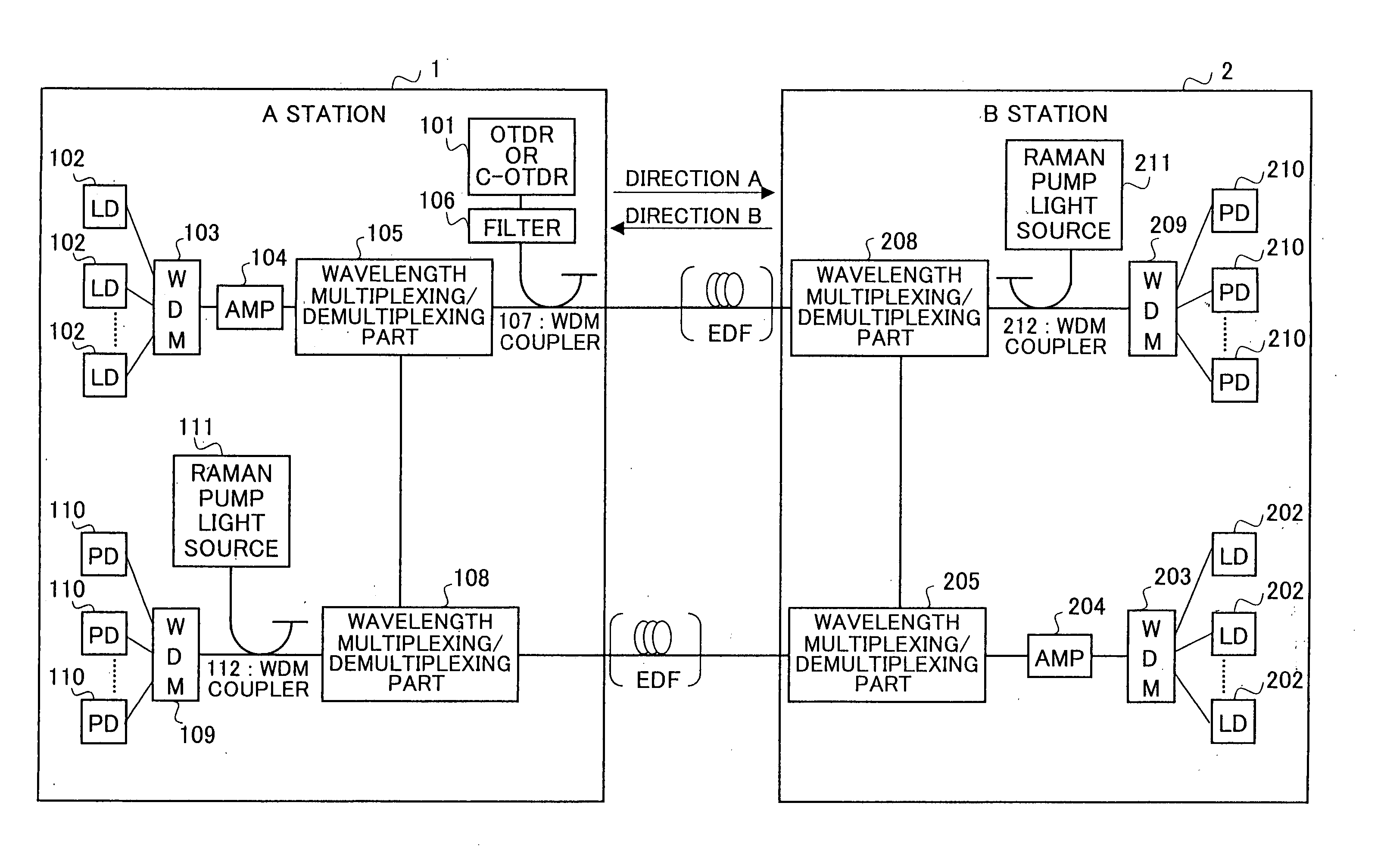
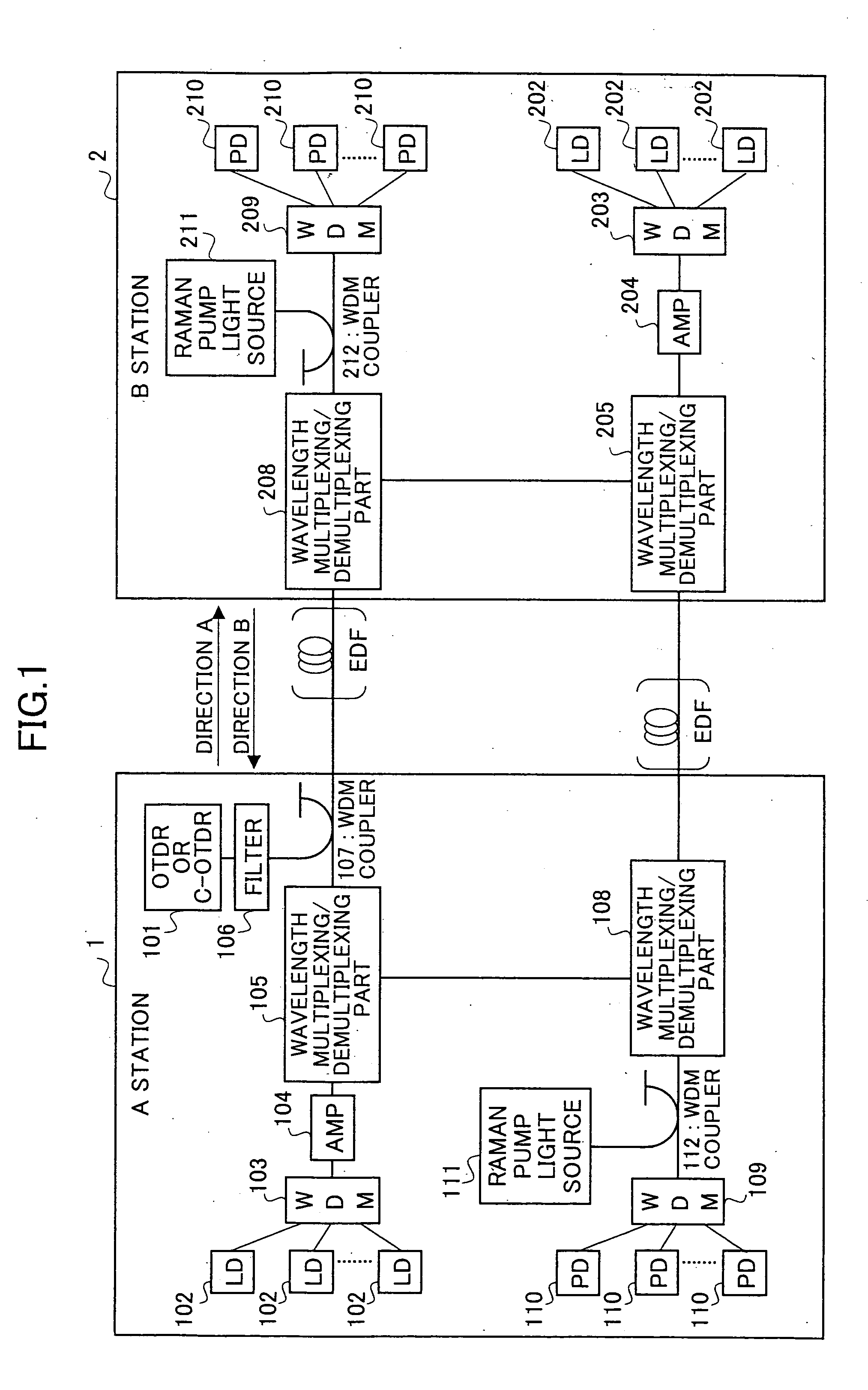
[0051]FIG. 2 is a figure for explaining the OTDR measurement method according to the first embodiment of the present invention. As shown in FIG. 2, the wavelength multiplexing / demultiplexing parts 105 and 108 are not provided in this embodiment.
[0052] According to the first embodiment shown in FIG. 2, light of 1650 nm band (λb) is used as the OTDR signal light. The wavelength range of the OTDR signal light in this embodiment is 1600-1700 nm. In this embodiment, C-band main signal light (λa 1550 nm band) emitted from the A station 1 is used as pump light to Raman amplify OTDR signal light (λb: 1650 nm band) emitted from the OTDR 101, so that the dynamic range is increased. That is, as shown in FIG. 3, since the light of 1650 nm band can be Raman amplified by the light of 1550 nm band, the light emitted from the main signal light source can be used as the Raman pump light for OTDR signal light. The example in which 1550 nm band light is Raman amplified by 1450 nm band light shown in ...
second embodiment
[0054]FIG. 4 is a figure for explaining an OTDR measurement method according to the second embodiment of the present invention.
[0055] In the second embodiment, light of 1550 nm band (λa) that is the same as the main signal light is used as the OTDR signal light. The OTDR signal light is Raman amplified by using pump light (λc 1450 nm band) emitted from the Raman pump light source 111 that is usually used for Raman amplifying signal light transmitted in the B direction, so that the distance of OTDR measurement is increased. The wavelength range of the OTDR signal light in this embodiment is 1500-1600 nm.
[0056] In this embodiment, the wavelength multiplexing / demultiplexing parts 105 and 108 function as optical switches 12 and 13 respectively. When OTDR measurement is not performed, the optical switch 12 transmits the main signal light emitted from the AMP 104 over the A line. When OTDR measurement is not performed, the optical switch 12 cuts off the main signal light emitted from th...
third embodiment
[0059]FIG. 5 is a figure for explaining an OTDR measurement method according to the third embodiment of the present invention.
[0060] In the third embodiment, light of 1650 nm band (λb) is used as the OTDR signal light. The wavelength range of the OTDR signal light in this embodiment is 1600-1700 nm. The OTDR signal light (λb: 1650 nm band) from the OTDR 101 is Raman amplified by using the main signal light (λa: 1550 nm band) from the A station light source. Further, the main signal light (λa: 1550 nm band) used for amplifying the OTDR signal light is Raman amplified by using pump light (λc: 1450 nm band) emitted from the Raman pump light source 111. That is, λa is pumped by using first-order Stokes wave of λc, so that λb is pumped by using the original power of λa as first-order Stokes wave and using the power of λa pumped by λc as second-order Stokes wave. Accordingly, the OTDR signal light is amplified so that dynamic range is enlarged and the distance of OTDR measurement is incr...
PUM
 Abstract
Description
Claims
Application Information
 - R&D
- Intellectual Property
- Life Sciences
- Materials
- Tech Scout
- Unparalleled Data Quality
- Higher Quality Content
- 60% Fewer Hallucinations
Browse by: Latest US Patents, China's latest patents, Technical Efficacy Thesaurus, Application Domain, Technology Topic, Popular Technical Reports.
© 2025 PatSnap. All rights reserved.Legal|Privacy policy|Modern Slavery Act Transparency Statement|Sitemap|About US| Contact US: help@patsnap.com


