
Integrated tire rim airbag system

Inactive Publication Date: 2005-05-26
DROEGEMUELLER DAVID S
View PDF8 Cites 16 Cited by
  • Summary
  • Abstract
  • Description
  • Claims
  • Application Information

AI Technical Summary

Benefits of technology

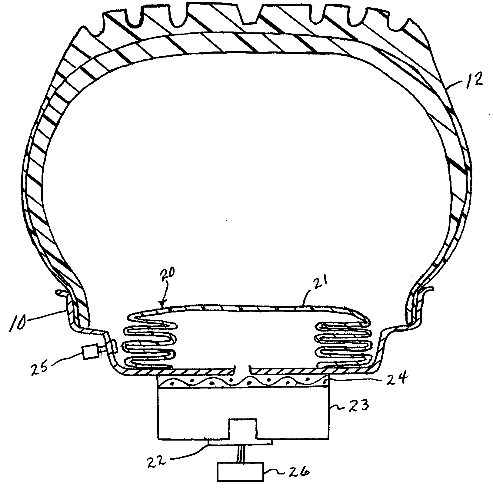
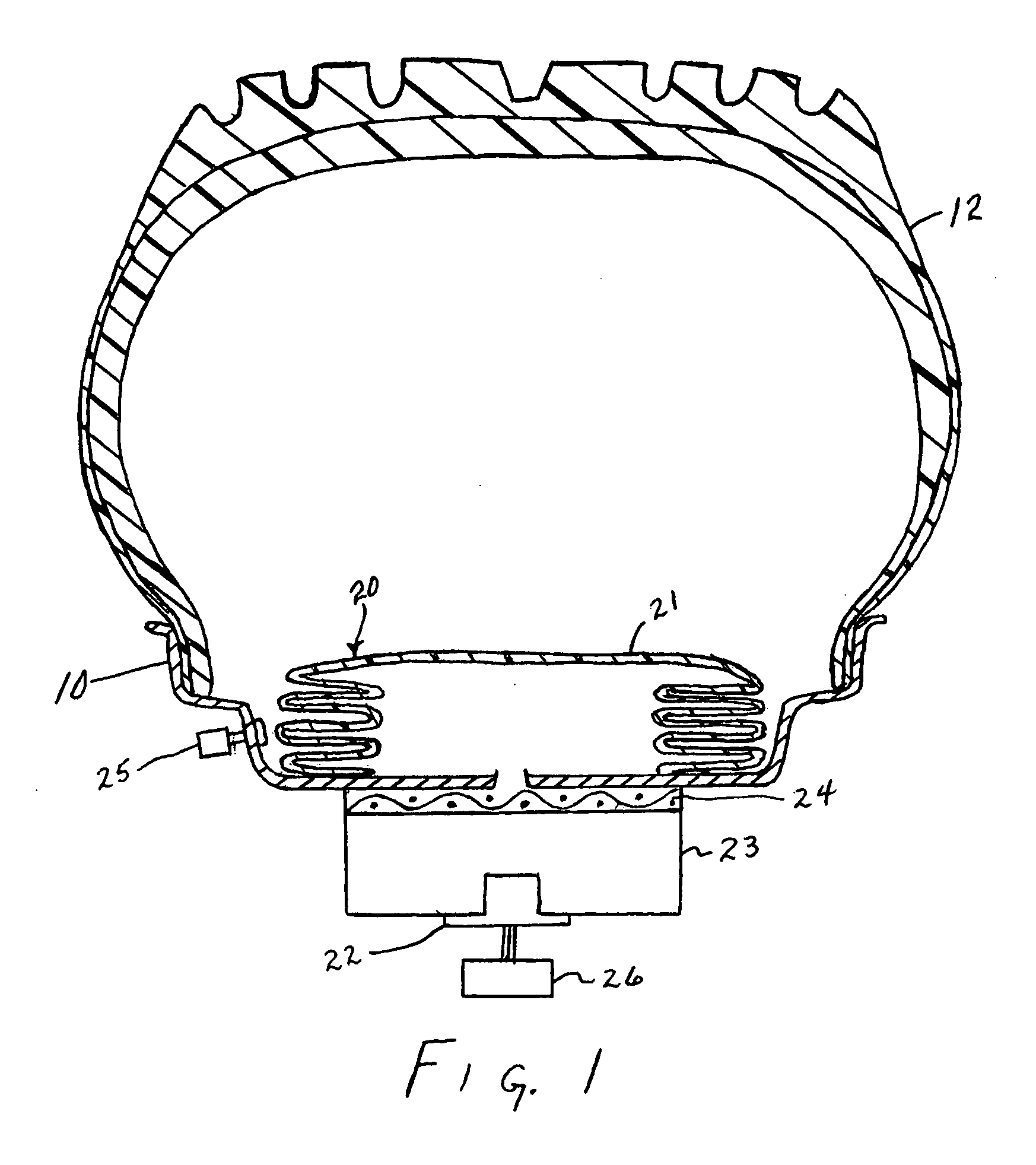
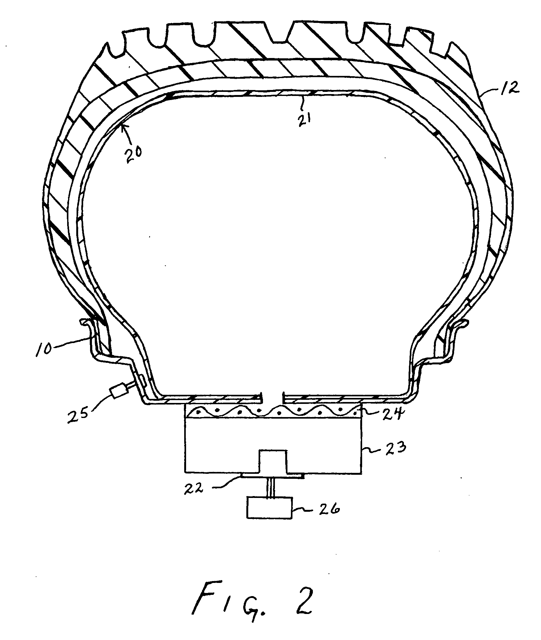
[0012] In accordance with the present invention there is provided an improved safety system for an inflated vehicle tire. The system includes a light-weight airbag secured to the tire rim inside the tire. In the event of rapid loss of air pressure from the tire, the airbag quickly inflates and simulates the profile of the tire with a wear surface available to support the vehicle until the driver is able to bring the vehicle under control and to a stop in a safe manner.

Problems solved by technology

When vehicle tires have a blowout, or experience other types of catastrophic failure, this presents a very dangerous condition for the driver and other occupants of the vehicle.
The rapid deflation of a vehicle tire can result in loss of ability of the driver to control the vehicle.
Oftentimes, loss of control results in an accident with the possibility of serious injuries or death.
The system would not, however, be able to maintain a predetermined pressure in a tire which has a blowout or other catastrophic failure because the system requires an intact tire as the final reservoir.
This system would not provide the safety needed in the event a tire completely failed.
This system adds a considerable amount of weight to the wheel.
The liner is placed inside the tire and is said to lose air slowly when the tire loses air pressure.
It does not provide a wear surface for the tire.

Method used


Image

  • Integrated tire rim airbag system
  • Integrated tire rim airbag system
  • Integrated tire rim airbag system

Examples


Embodiment Construction

[0016] In the drawings there is shown a wheel or tire rim 10 in which the airbag system 20 is contained. The airbag has a flat, low profile and is mounted close to the wheel rim so as to provide low centrifugal force. The airbag could also be designed to have a donut shape or a flat pancake shape.

[0017] It is also possible for the airbag to include multiple cells with one-way check valves between them to maintain pressure in the majority of the cells in the event an object (such as a large spike) which might also puncture the airbag when it is deployed.

[0018] The airbag system, in one embodiment, includes the inflatable bag 21, an igniter 22, a container 23 for solid propellant (e.g. sodium azide or equivalent), a tire pressure monitoring system 25, and a controller 26. The tire pressure monitoring system 25 is attached to the wheel valve stem and it continuously monitors tire pressure. It transmits a radio frequency signal to the controller 26 when a loss of tire pressure is dete...


PUM


Abstract

An airbag system secured to the tire rim inside a tire. The airbag is normally in a collapsed state close to the rim. The airbag is inflated with pressurized gas in the event of a tire failure. The inflated bag generally conforms to the inner walls of the tire to support the weight of the vehicle and enable the vehicle to be safely stopped. The bag has wear surfaces composed of durable material such as nylon or Kevlar fibers.

Description

CROSS-REFERENCE TO RELATED APPLICATIONS [0001] This application is based upon, and claims the benefit of, my Provisional Application No. 60 / 519,484, filed Nov. 13, 2003.FIELD OF THE INVENTION [0002] This invention relates to vehicle tire systems. More particularly, this invention relates to safety systems in the event of a tire blowout or other catastrophic tire failure situations. BACKGROUND OF THE INVENTION [0003] When vehicle tires have a blowout, or experience other types of catastrophic failure, this presents a very dangerous condition for the driver and other occupants of the vehicle. The rapid deflation of a vehicle tire can result in loss of ability of the driver to control the vehicle. Oftentimes, loss of control results in an accident with the possibility of serious injuries or death. [0004] U.S. Pat. No. 6,601,625 (Rheinhardt) describes a vehicle wheel system which includes a high pressure reservoir (i.e. tank) on the rim. The system is designed to release air into the ti...

Claims


Application Information

Patent Timeline
IPC IPC(8): B60C17/02B60C23/00
CPCB60C23/004B60C17/02
Inventor DROEGEMUELLER, DAVID S.
Owner DROEGEMUELLER DAVID S
Learn More