
Method for redundancy backup of signaling link in ip network

a signaling link and backup technology, applied in the field of redundancy backup of signaling links in ip network, can solve the problems of data disorder and loss, protocol has not yet offered a good solution, and the transfer rate of the primary link and the backup link is large, so as to avoid data disorder and loss

Active Publication Date: 2005-05-19
OPEN INVENTION NEWTORK LLC
View PDF2 Cites 9 Cited by
  • Summary
  • Abstract
  • Description
  • Claims
  • Application Information

AI Technical Summary

Benefits of technology

[0007] The present invention aims at effectively avoiding data disorder and loss during switch between the primary and backup links in SIGTRAN protocol and proposes a method for implementing signaling link redundancy based on SIGTRAN adaptation model.
[0017] In the proposed method, two ASPs are created for the same AS in the host at the IP network side, and all user adaptation protocols share ASPSM and ASPTM messages so that the states of the two ASPs can become active and inactive respectively, thus to implement two signaling links for serving the same traffic. When switch is carried out, SCTP association can use “graceful close”, and the SCTP itself will make sure to send out all the data remaining in its buffer and the applications on the SCTP will also send subsequent data in order after learning the remaining data are all sent out, thus sequential delivery for the data can be guaranteed. This method can avoid data loss and disorder, and the speed for switch can be ensured because the backup link will be notified immediately after the data on the primary link are sent out.

Problems solved by technology

Since different connections over IP networks are very likely to traverse across different networks, there can be great difference between the transfer rate of the primary link and that of the backup link.
During switch, the late transmitted data may arrive earlier, which can lead to data disorder and loss.
Under this situation, the protocol has not yet offered a good solution to avoid the data loss and disorder during switch.

Method used


Image

  • Method for redundancy backup of signaling link in ip network
  • Method for redundancy backup of signaling link in ip network
  • Method for redundancy backup of signaling link in ip network

Examples


Embodiment Construction

[0026] Detailed description of the proposed method will be given below, in conjunction with accompanying drawings and embodiments.

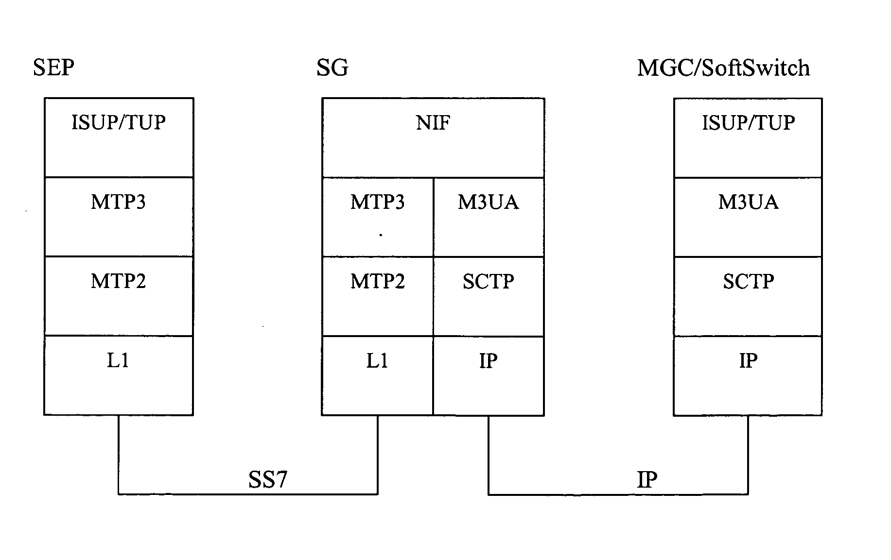
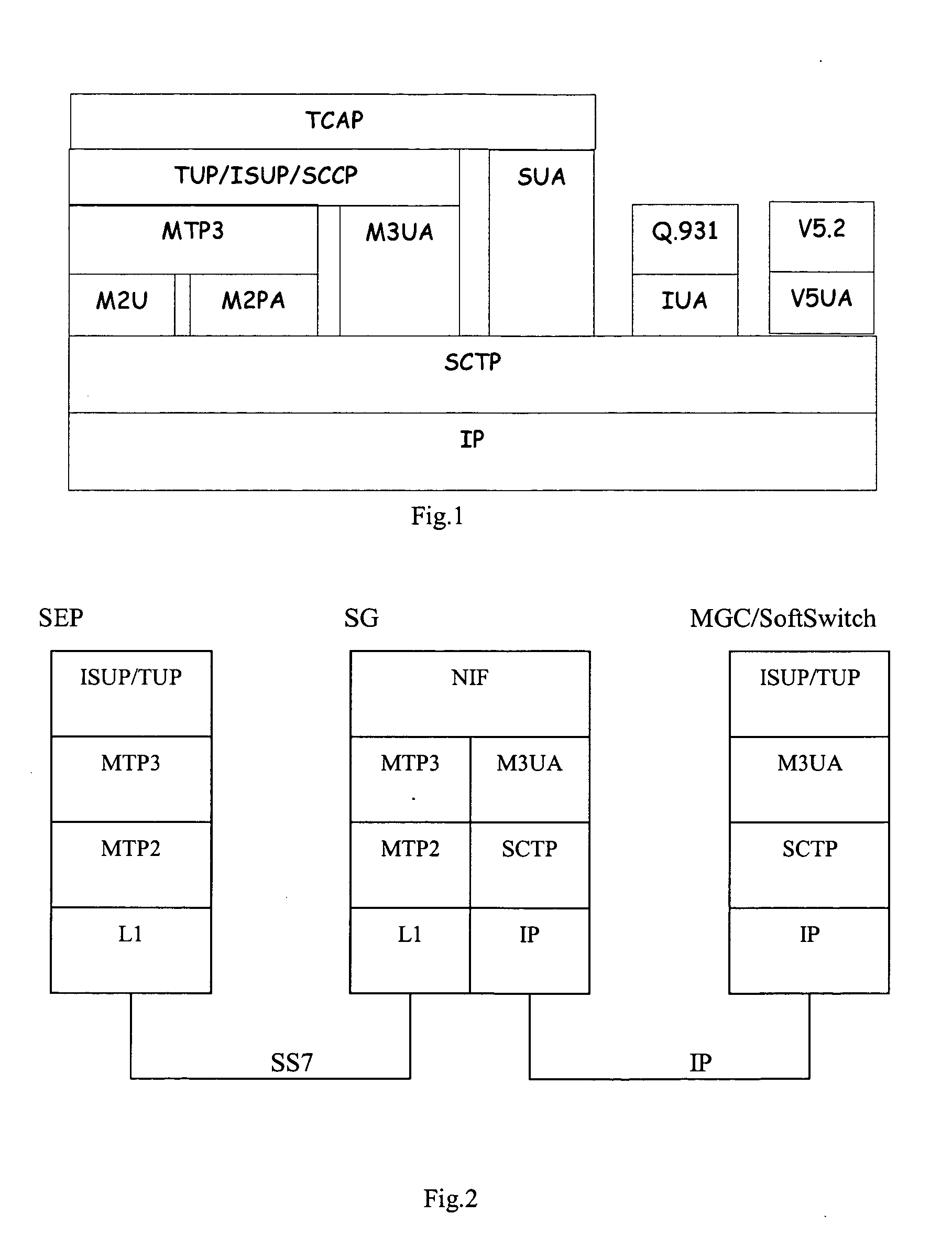
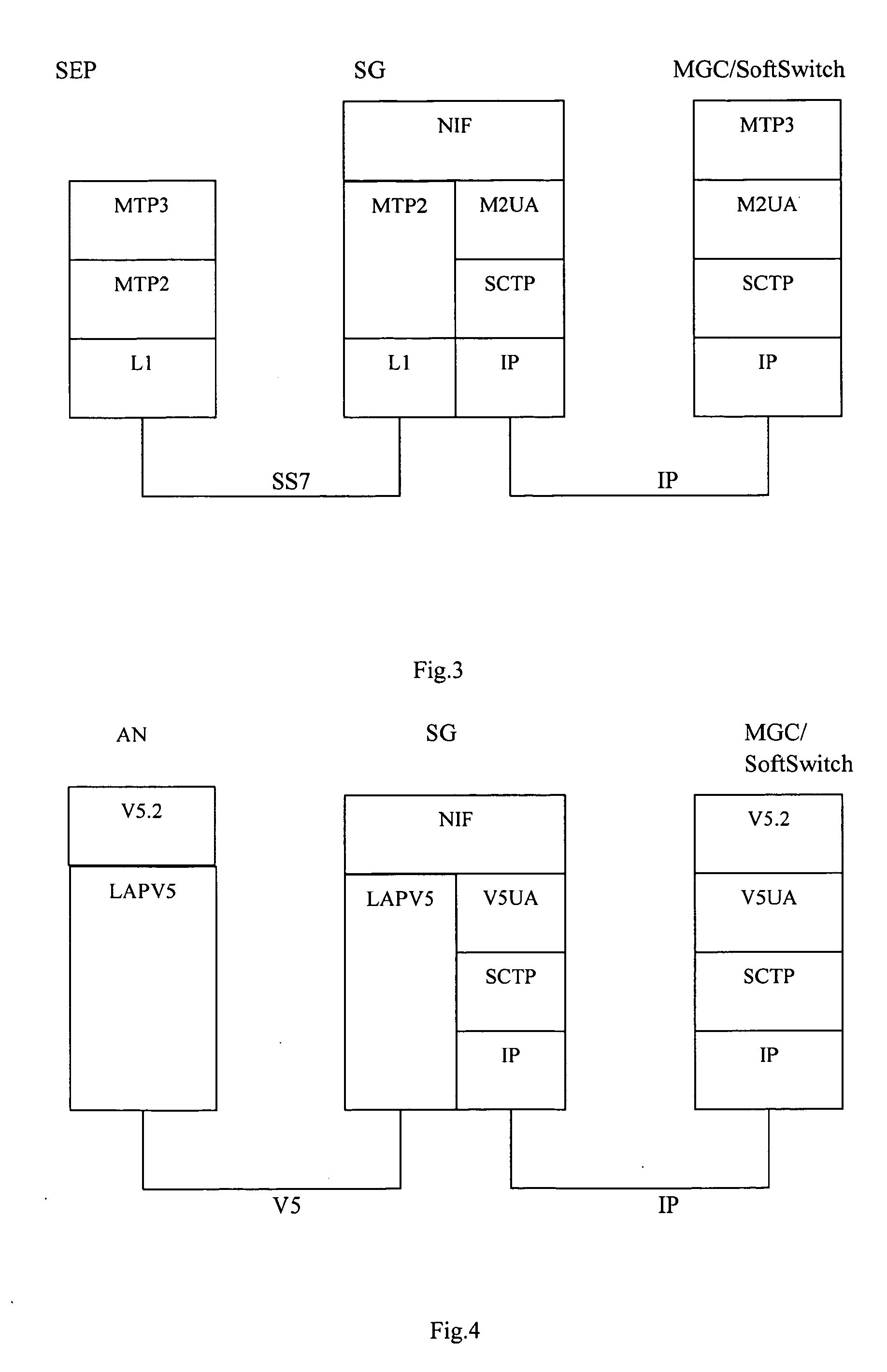
[0027]FIG. 1 has been explained before and won't be elaborated any more herein. FIG. 2 to FIG. 6 illustrate the physical layer and signaling protocols involved in adapting various signaling messages of conventional telecommunication networks into IP networks. It can be seen that all protocols have the common ground of taking SCTP / IP as their lower-layer carrier protocol. Different signaling can use different adaptation protocols according to practical requirement. For instance, in FIG. 2, #7 signaling adopts M3UA adaptation protocol, wherein SEP represents Signaling End Point, ISUP represents ISDN User Part, TUP represents Telephone User Part, MTP3 represents Message Transfer Part Level 3, MTP2 represents Message Transfer Part Level 2, L1 represents Message Transfer Part Level 1, NIF represents Nodal Interworking Function, M3UA represents MTP3 User Adapt...


PUM


Abstract

The invention discloses a method for implementing signaling link redundancy in IP networks. Two ASPs are created for the same AS in the host at the IP network side, and all user adaptation protocols share ASPSM and ASPTM messages so that the states of the two ASPs can become active and inactive respectively, thus to implement two signaling links for serving the same traffic. When switch is initiated, SCTP association can be closed by using “graceful close”, and the SCTP itself will make sure to send out all the data remaining in its buffer and its higher-layer applications will also send subsequent data in order after learning the remaining data are all sent out, thus sequential delivery for the data can be guaranteed. This method can avoid data loss and disorder, and the speed for switch can be ensured because the backup link will be notified immediately after the data on the primary link are sent out.

Description

FIELD OF THE INVENTION [0001] The present invention relates generally to a method for accurate data delivery between IP networks and conventional telecommunication networks, and more particularly, to a method for implementing signaling link redundancy in IP networks. BACKGROUND OF THE INVENTION [0002] In order to transit smoothly from conventional telecommunication networks to next-generation IP networks, IETF (Internet Engineering Task Force) proposes a set of signaling transport (SIGTRAN) protocol model, for adapting various signaling messages in conventional telecommunication networks into IP networks, herein adapting specifically means replacing the previous information exchanges (including primitive, message and etc) between software modules put together with standard protocol so that two software modules can be separated completely without making modification. As shown in FIG. 1, signaling in conventional telecommunication network includes SS7 (Signaling System 7), DSS1 (Digit...

Claims


Application Information

Patent Timeline
IPC IPC(8): H04B1/74H04B7/26H04L1/22H04L12/28H04L69/40H04M1/24H04M3/08H04Q7/20
CPCH04L69/16H04L69/163H04L69/40
Inventor XI, MIN
Owner OPEN INVENTION NEWTORK LLC
Learn More