Temperature sensor circuit

Inactive Publication Date: 2005-05-19
SEIKO INSTR INC
View PDF7 Cites 11 Cited by
  • Summary
  • Abstract
  • Description
  • Claims
  • Application Information

AI Technical Summary

Benefits of technology

[0008] In order to attain the above-mentioned object, according to the present invention, there is provided a temperature sensor circuit including: at least a constant current source; and a base-to-emitter voltage multiplication circuit constructed by a bipolar transistor and resistors, in which a base current error compensation circuit is provided so as to eliminate an error of the base current of the bipolar transistor caused to flow through the resistor. In addition, the temperature sensor circuit of the present invention has such a structure that a resistance value of the resistor that determines an output voltage VOUT may be controlled.
[0009] By adopting the above-mentioned structure, the present invention can provide the temperature sensor circuit capable of obtaining a highly precise output voltage as a desired output voltage and which is highly precise in output voltage.

Problems solved by technology

Thus, when there is made a request to output an arbitrary voltage to the output terminal 10, it is difficult to respond to this request.
Consequently, it is difficult to set the output voltage VOUT as aimed using Equation (2).
Moreover, it is difficult to set the output voltage VOUT as aimed owing to the dispersion in the characteristics of the bipolar transistor 12 and the characteristics of the two resistors 13 and 14.

Method used


Image

  • Temperature sensor circuit
  • Temperature sensor circuit
  • Temperature sensor circuit

Examples


first embodiment

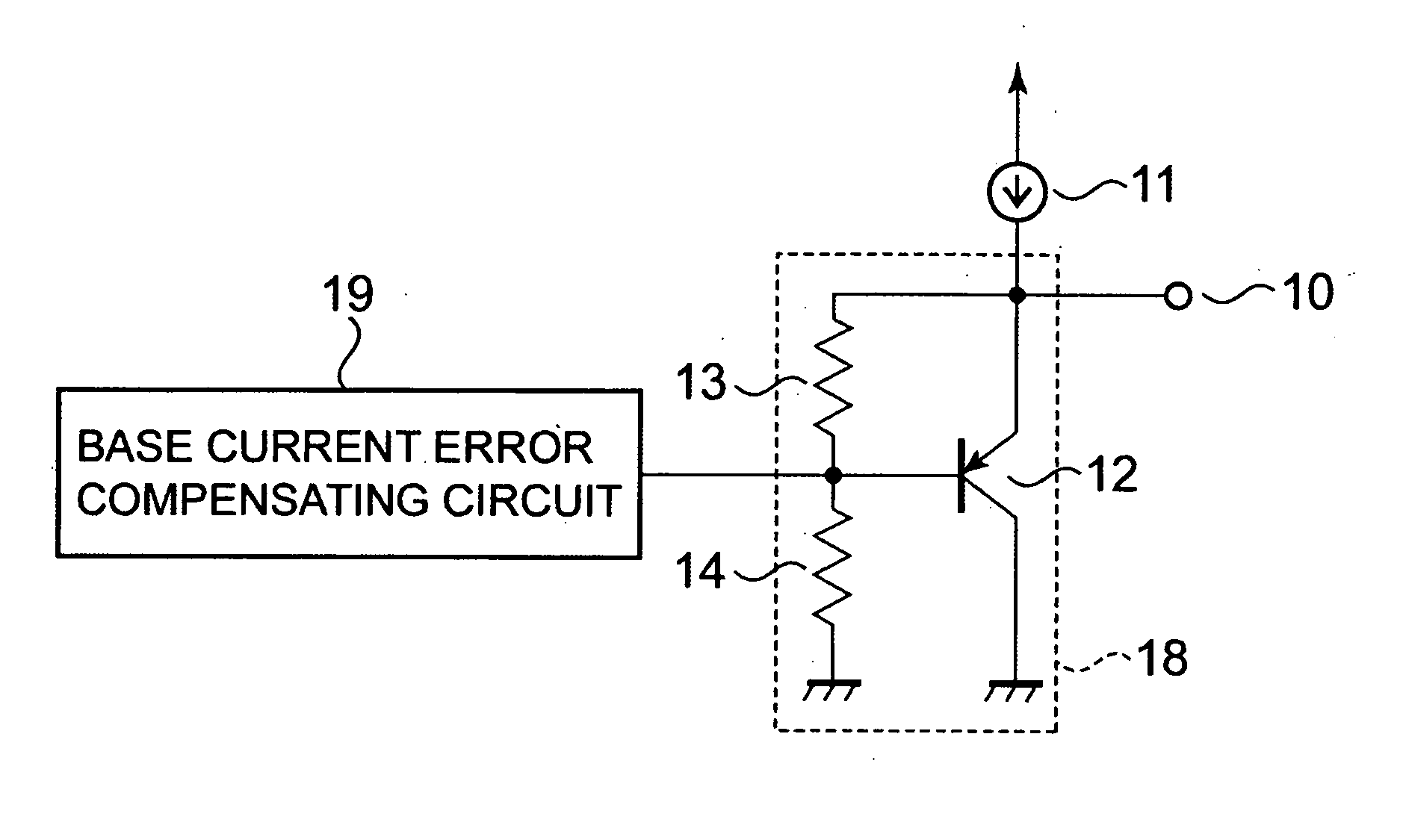
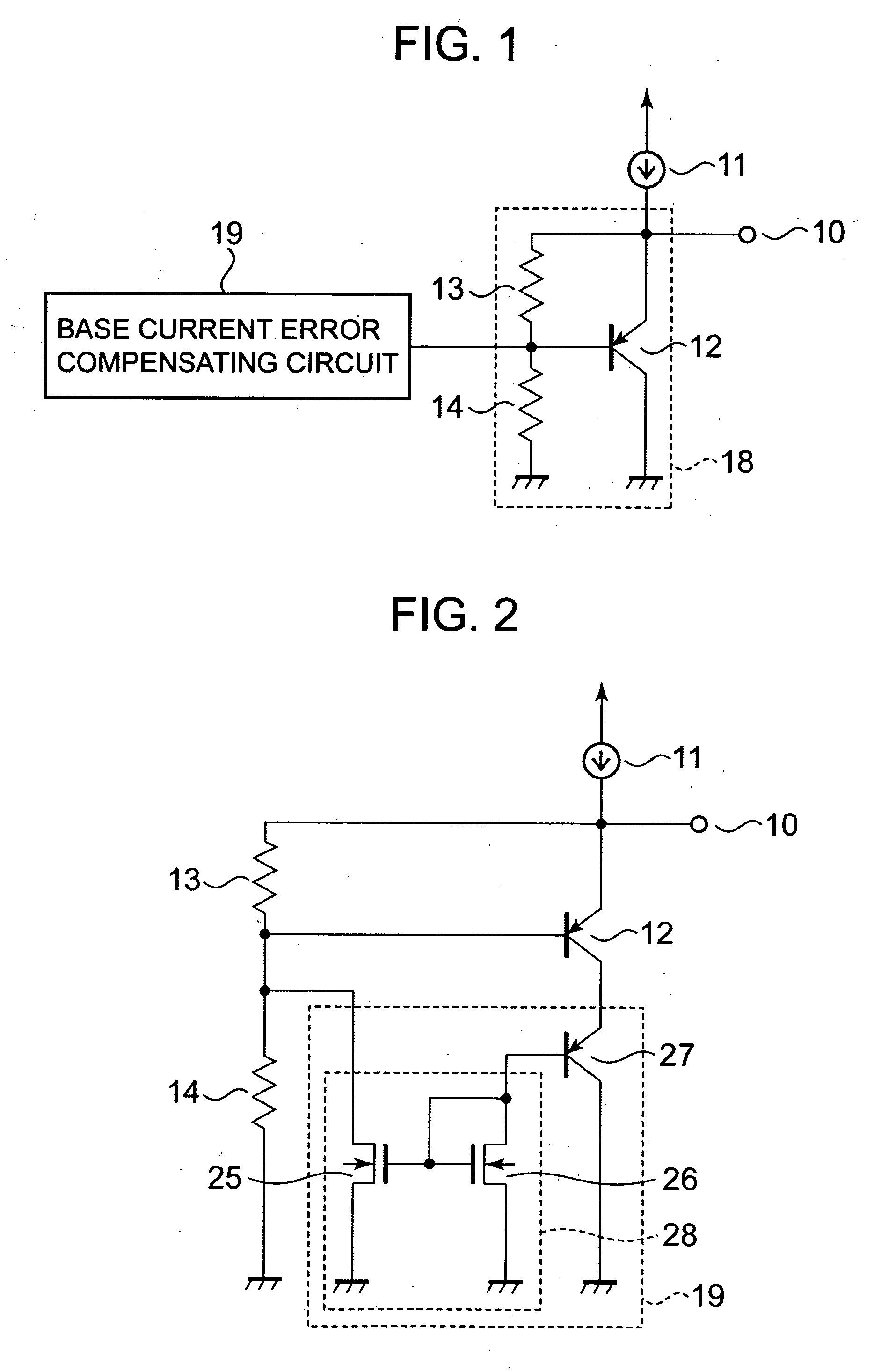
[0018] A temperature sensor circuit according to a first embodiment of the present invention is shown in FIG. 1. The temperature sensor circuit of the first embodiment shown in FIG. 1 is such that a base current error compensation circuit 19 is provided in the temperature sensor circuit shown in FIG. 7. For example, the base current error compensation circuit 19, as shown in FIG. 2, includes a bipolar transistor 27 having a base connected to a drain of a second N-channel MOS transistor 26, and a current mirror circuit 28 constituted by a first N-channel MOS transistor 25 and the second N-channel MOS transistor 26. Note that it is assumed that the characteristics of the bipolar transistors 12 and 27 are equal to each other and their emitter area sizes are also equal to each other, and the characteristics of the first and second N-channel MOS transistors 25 and 26 are equal to each other and their transistor sizes are equal to each other. An emitter of the bipolar transistor 27 is con...

second embodiment

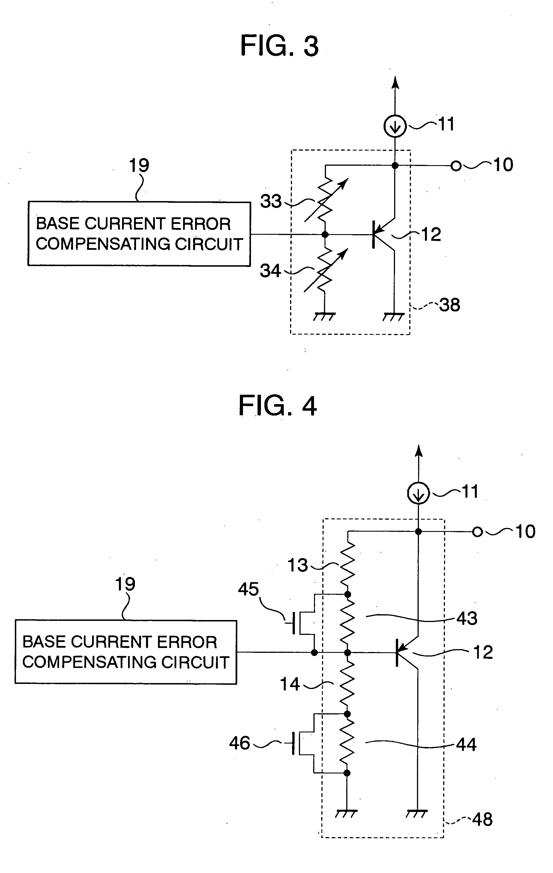
[0019] A temperature sensor circuit according to a second embodiment of the present invention is shown in FIG. 3. In the temperature sensor circuit of the first embodiment, the first and second resistors 13 and 14 are provided as fixed resistors. In the case of the first embodiment, however, if the shift in the output voltage VOUT due to the dispersion in characteristics of the bipolar transistors 12 and 17 and characteristics of the first and second resistors 13 and 14 is taken into consideration, then the fine adjustment of the output voltage VOUT is essential to the design of the temperature sensor circuit. In this case, at least one of the first and second resistors 13 and 14 of the first embodiment is replaced with a variable resistor, thereby allowing the output voltage VOUT to be finely adjusted. As a result, the output voltage VOUT can be set with more highly precision as compared with the case of adoption of the fixed resistors.

third embodiment

[0020] A temperature sensor circuit according to a third embodiment of the present invention is shown in FIG. 4. In the temperature sensor circuit shown in FIG. 4, the variable resistors of the temperature sensor circuit according to the second embodiment are constructed by MOS switches. With this circuit structure, the resistance values of the first or second resistors may be finely adjusted by ON / OFF operation of the MOS switches at a stage of post circuit production, thereby being capable of setting the output voltage VOUT precisely.


PUM


Abstract

To provide a temperature sensor circuit capable of obtaining a highly precise output voltage as a desired output voltage. The temperature sensor circuit includes: at least a constant current source; and a base-to-emitter voltage multiplication circuit constructed by a bipolar transistor and resistors, in which a base current error compensation circuit is provided so as to eliminate an error of the base current of the bipolar transistor caused to flow through the resistor. Further, the temperature sensor circuit of the present invention has such a structure that a resistance value of the resistor that determines an output voltage may be controlled.

Description

BACKGROUND OF THE INVENTION [0001] 1. Field of the Invention [0002] The present invention relates to a temperature sensor circuit configured with a semiconductor integrated circuit. [0003] 2. Description of the Related Art [0004] A conventional temperature sensor circuit configured with a semiconductor integrated circuit is shown in FIG. 6. In general, in a temperature sensor circuit, a collector and a base of a bipolar transistor 12 are set at the same electric potential, and an emitter thereof is connected to a constant current source 11. That is to say, the bipolar transistor 12 is diode-connected, thereby outputting a base to emitter voltage (hereinafter referred to as “a VBE” for short) of the bipolar transistor 12 to an output terminal 10. In this case, it is generally known that the VBE is independent of a current value of the constant current source 11, and hence has a certain constant voltage value. Thus, when there is made a request to output an arbitrary voltage to the ou...

Claims


Application Information

Patent Timeline
IPC IPC(8): G01K7/01G01K7/00H01L21/822H01L27/04H03K5/00
CPCG01K7/01G01K7/00
Inventor SATO, YUTAKA
Owner SEIKO INSTR INC
Why Eureka
Try Eureka