Method and apparatus for multi-beam optical scanning capable of effectively adjusting a scanning line pitch

a multi-beam optical scanning and scanning line technology, applied in the direction of beam/ray focussing/reflecting arrangement, instruments, electric discharge tubes, etc., can solve the problems of cumulative errors in mounting positions, failure to form a desired shape, and deviation of the dot positional in the sub-scanning direction

Inactive Publication Date: 2005-05-19
ONO NOBUAKI +4
View PDF5 Cites 27 Cited by
  • Summary
  • Abstract
  • Description
  • Claims
  • Application Information

AI Technical Summary

Benefits of technology

[0017] In view of the foregoing, it is an object of the present invention to provide a novel optical scanning apparatus which produces multiple laser light beams having a preferable beam pitch without causing deviations in image density.
[0018] Another object of the present invention is to provide a novel image forming apparatus which includes an optical scanning apparatus that produces multiple laser light beams having a preferable beam pitch without causing deviations in image density.

Problems solved by technology

While plastic materials are superior for mass production, they often fail in forming a desired shape due to an uneven temperature provided inside a mold tool during a mold process or an uneven cooling applied after the removal from the mold tool.
This can cause a deviation of dot positional in the sub-scanning direction if an optical device is not held in a preferable manner.
When, the optical devices are mounted to the optical housing, cumulative errors in the mounting positions can often occur and they become a non-negligible deviation in dot position in the sub-scanning direction on the photosensitive surface.
This phenomenon is a crucial drawback, particularly, for a tandem-type full color copying apparatus.
Thus, if dot positions of the latent images for the cyan, magenta, yellow, and black colors are deviated in the sub-scanning direction, a phenomenon of color deviation occurs and accordingly image quality is degraded.
Errors in scanning line positioning occur mainly because of deviations of the multiple laser light beams in the sub-scanning direction.

Method used


Image

  • Method and apparatus for multi-beam optical scanning capable of effectively adjusting a scanning line pitch
  • Method and apparatus for multi-beam optical scanning capable of effectively adjusting a scanning line pitch
  • Method and apparatus for multi-beam optical scanning capable of effectively adjusting a scanning line pitch

Examples


Embodiment Construction

[0047] In describing preferred embodiments illustrated in the drawings, specific terminology is employed for the sake of clarity. However, the disclosure of this patent specification is not intended to be limited to the specific terminology so selected and it is to be understood that each specific element includes all technical equivalents that operate in a similar manner.

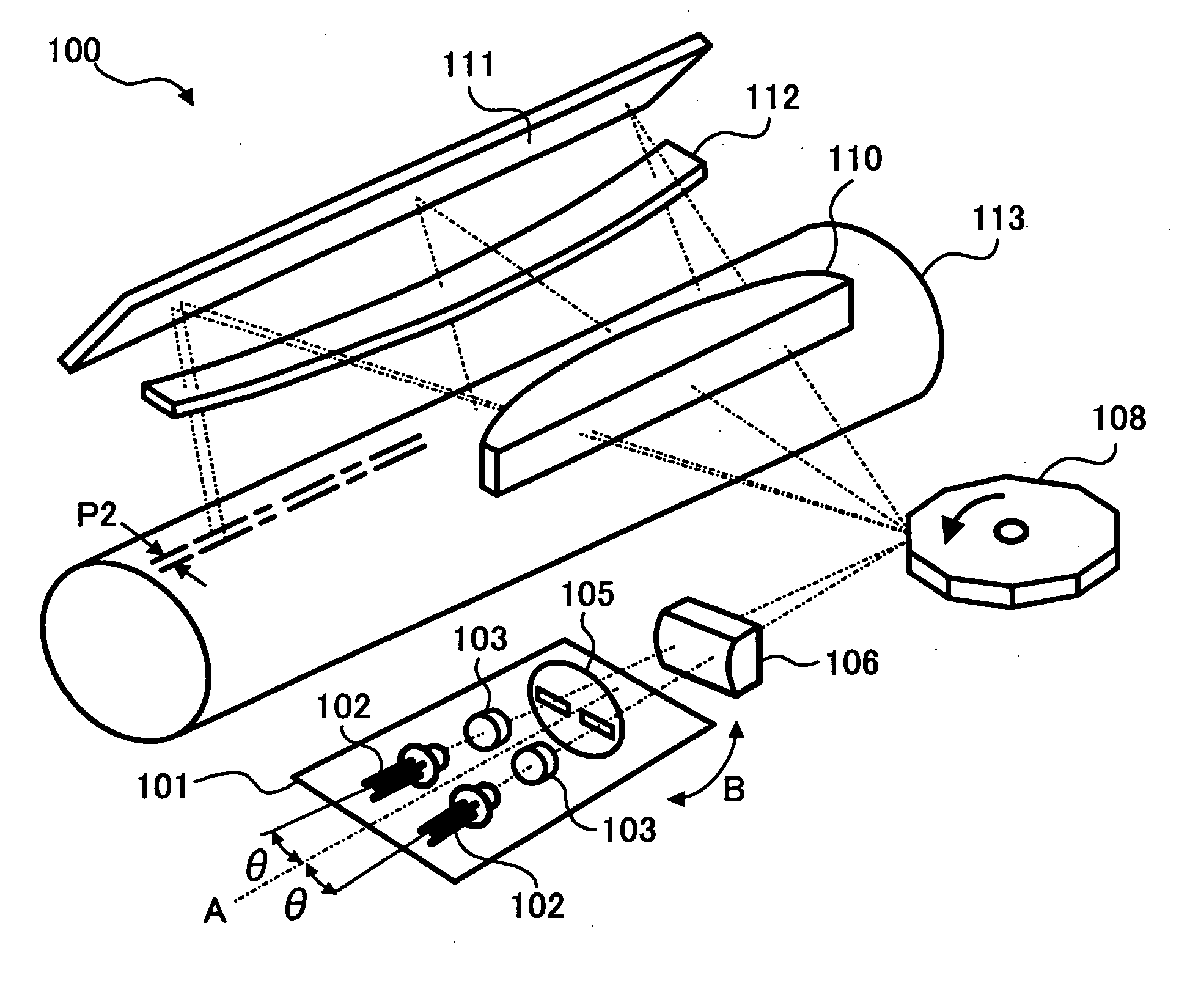
[0048] Referring now to the drawings, wherein like reference numerals designate identical or corresponding parts throughout the several views, particularly as to FIGS. 5-7, a description is made of a multi-beam optical scanning apparatus 100 according to a preferred embodiment of the present invention. As shown in FIG. 5, the multi-beam optical scanning apparatus 100 is provided with a laser light source unit 101 that includes two light sources 102 (e.g., laser diodes) and a corresponding pair of coupling lenses 103 and an aperture element 105 having two slits. The multi-beam optical scanning apparatus 100 further...


PUM


Abstract

An optical scanning apparatus includes light sources, an aperture having, and coupling lenses. Numbers of the light sources and the coupling lenses are equal to each other and the apparatus satisfies an inequality 12.7<(D×β0×m0×dpi) / (2×NA)<38.1 and an equation β0=(β+−β−) / (n−1), wherein D represents a width of the slit of the aperture, β0 represents a beam open angle, mo represents a total lateral magnification ratio, dpi represents a number of dots per inch, NA represents a numerical aperture, β+ represents a positive open angle, β− represents a negative open angle, and n represents the number. Further, an image forming apparatus using this optical scanning apparatus and an image forming method are provided.

Description

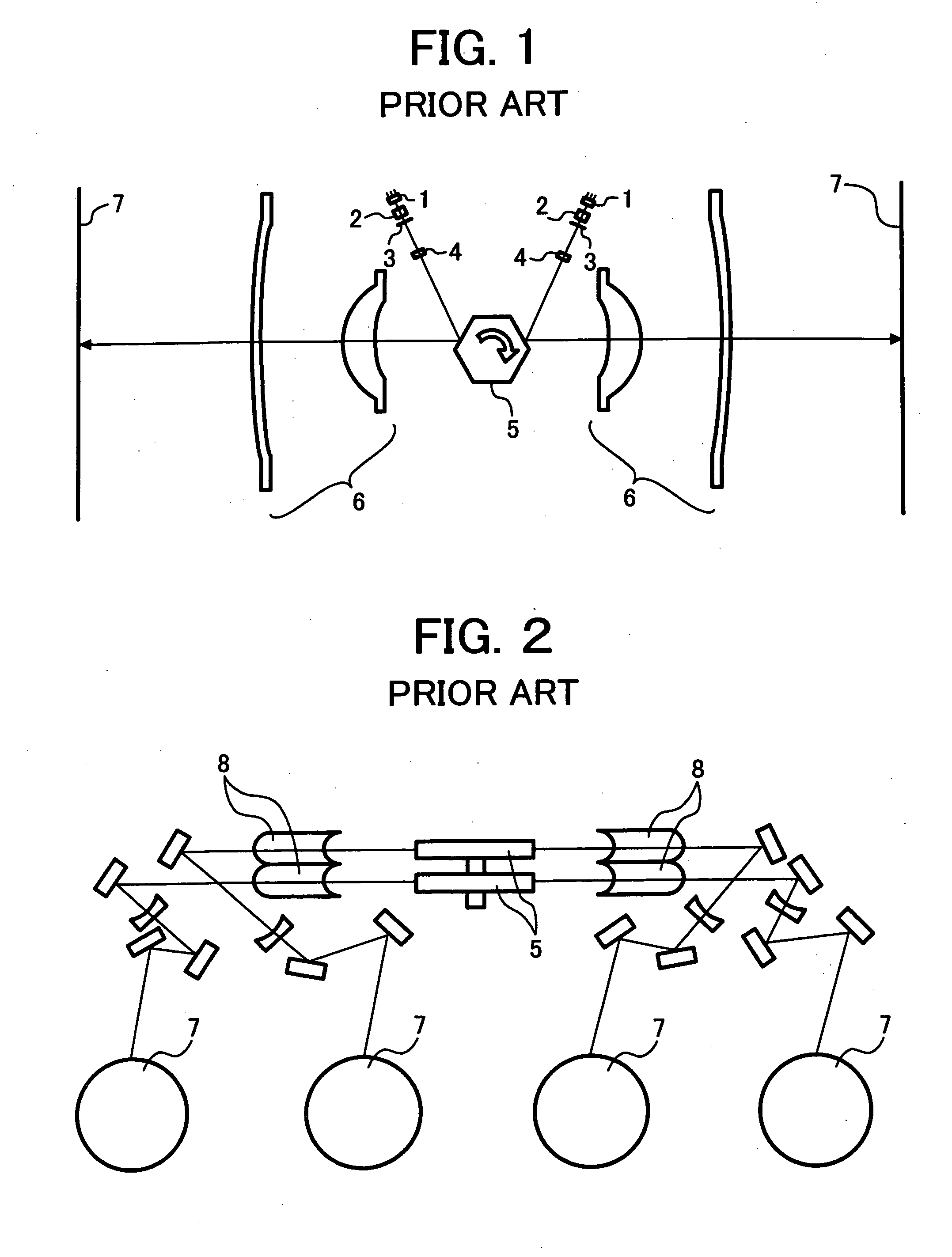
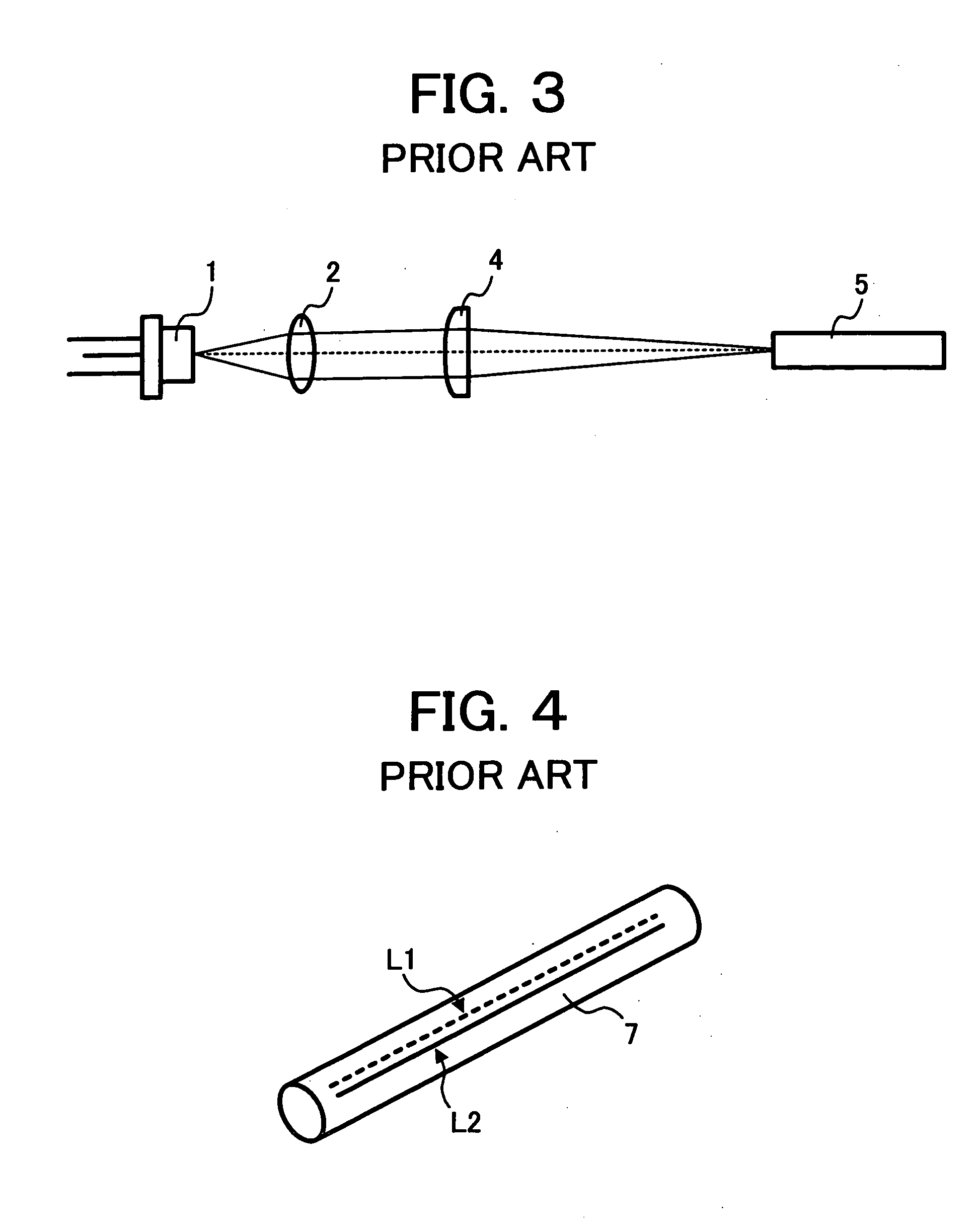
BACKGROUND OF THE INVENTION [0001] 1. Field of the Invention [0002] The present invention relates to a method and apparatus for multi-beam optical scanning, and more particularly to a method and apparatus for multi-beam optical scanning capable of generating multiple scanning beams for forming multiple latent images in a multi-color image forming apparatus and effectively adjusting scanning line pitches of the multiple scanning beams. [0003] 2. Discussion of the Background [0004] In recent years, a tandem-type color image forming apparatus has been developed, including an optical scanning system that emits multiple beams for basic printer colors in sequence. The optical scanning system uses a plurality of laser light sources for generating the color corresponding multiple beams and a plurality of optical components sets, which are integrated in a single-piece unit and are put into a single housing. The apparatus includes plural sets of a photosensitive member and a development unit ...

Claims


Application Information

Patent Timeline
Patent Type & Authority Applications(United States)
IPC IPC(8): G02B26/08B41J2/44G02B26/10G02B26/12H01J3/14H01J5/16H04N1/036H04N1/04H04N1/113H04N1/12H04N1/191H04N1/50
CPCG02B26/123G02B26/124H04N1/0402H04N1/0414H04N1/0437B41J2/473H04N1/1135H04N1/12H04N1/1911H04N1/506H04N1/0455
Inventor ONO, NOBUAKINAKAJIMA, TOMOHIROITABASHI, AKIHISATAKANASHI, KENICHIOHSUGI, TOMOYA
Owner ONO NOBUAKI
Why Eureka
Try Eureka