
Printer calibration method, printer and recording material

a printing method and printer technology, applied in the field of printing calibration methods, printers and recording materials, can solve the problems of calibration standards, above mentioned problems not coming, and raised calibration costs, and achieve the effect of making reliable calibration with eas

Inactive Publication Date: 2005-05-19
FUJIFILM HLDG CORP +1
View PDF6 Cites 17 Cited by
  • Summary
  • Abstract
  • Description
  • Claims
  • Application Information

AI Technical Summary

Benefits of technology

[0012] In view of the foregoing, a primary object of the present invention is to provide a calibration method for printers, which does not use a densitometer, but enables making reliable calibration with ease by the visual inspection.
[0013] Another object of the present invention is to provide a printer that can be calibrated with reliability without the need for any densitometer.
[0021] According to the present invention, the calibration patterns are compared with the reference patterns that are previously printed on the recording material to represent a number of density grades, so that even an less experienced operator can determine the actual optical density of the printer with reliability.
[0022] Since the reference patterns are printed on the same recording paper in the same way as the calibration patterns, the colors of the reference patterns will not look different from those of the calibration patterns, independently of the illumination light. Therefore, the reference patterns serve as reliable color samples.
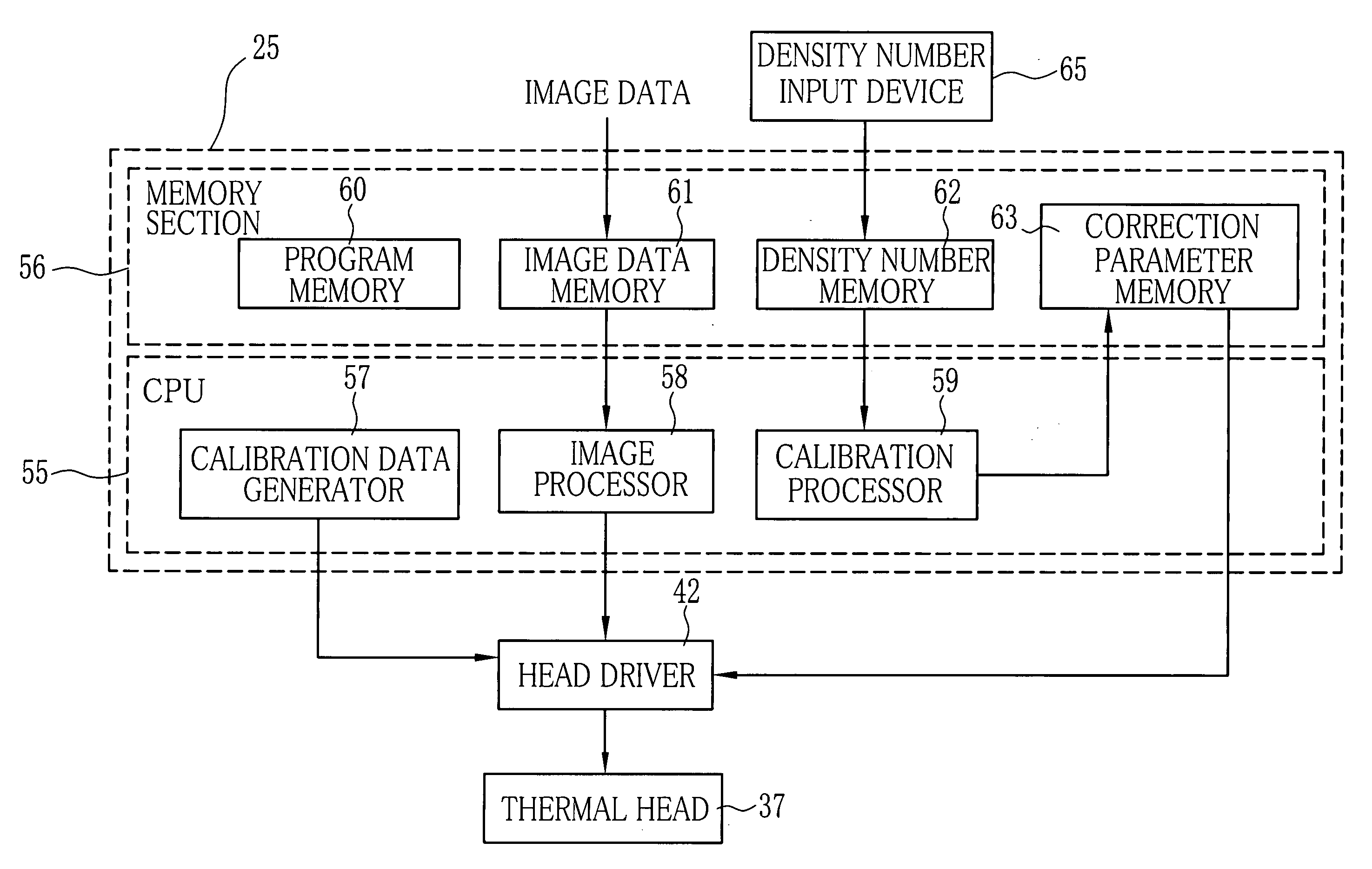
[0023] The print densities of the recording head are corrected on the basis of a difference between an optical density value of the actual density of each calibration pattern and the set value that is used for printing the calibration patterns. Therefore, there is no need for complicated calculations or operations. According to a preferred embodiment, the print densities are corrected automatically just by entering the density numbers, so anyone can make calibration of the color thermal printer without any difficulty.

Problems solved by technology

Because the calibration method using the densitometer needs the densitometer inside or outside the color thermal printer, the cost of calibration is raised by the cost of densitometer.
On the contrary, the above mentioned problems do not come up in those calibration methods which do not use the densitometer.
However, because the color samples suffer aging-related changes, like fading, they are unstable as the calibration standards.
Therefore, they are not reliable enough as the calibration standards.
Furthermore, since the visual inspection is largely dependent upon the experience of the inspector, it is difficult to achieve stable calibration.

Method used


Image

  • Printer calibration method, printer and recording material
  • Printer calibration method, printer and recording material
  • Printer calibration method, printer and recording material

Examples


Embodiment Construction

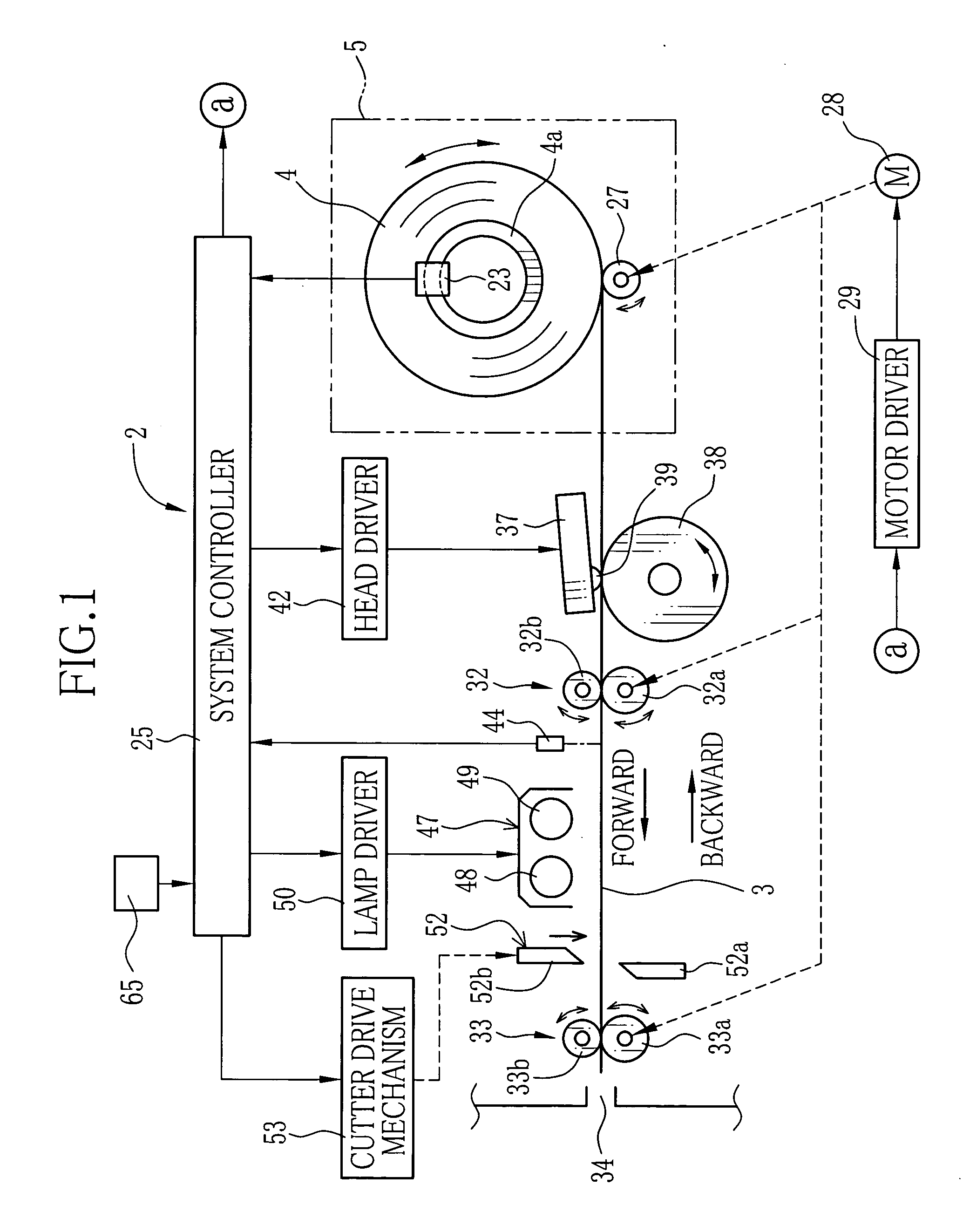
[0036]FIG. 1 shows a color thermal printer 2 according to an embodiment of the invention. The color thermal printer 2 uses a long web of color heat sensitive recording paper 3 as a recording material. The color heat sensitive recording paper 3 is sold as a recording paper roll 4 in the market, and the recording paper roll 4 is set in a roll chamber 5 of the color thermal printer 2.

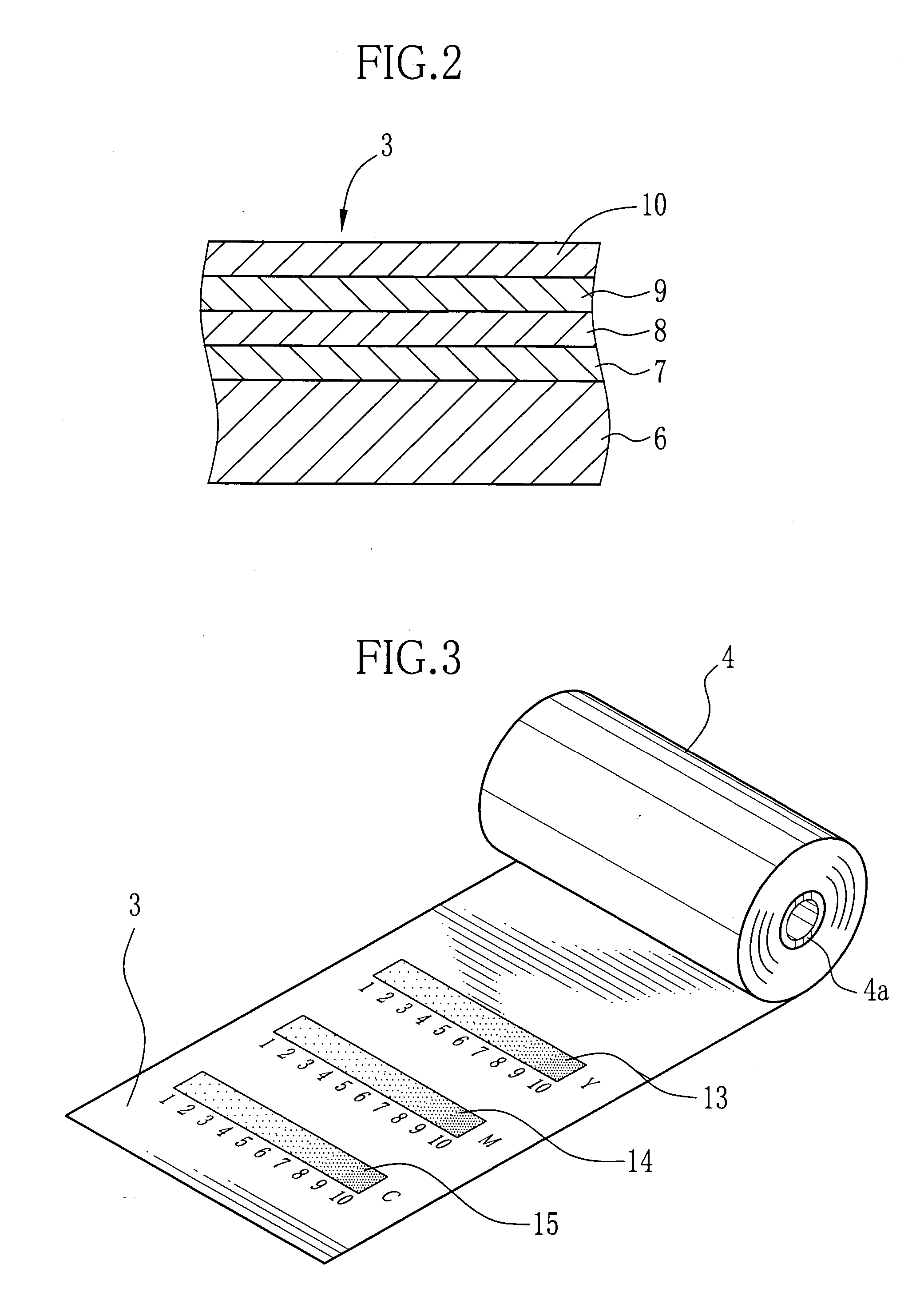
[0037] As shown in FIG. 2, the color heat sensitive recording paper 3 has three thermosensitive coloring layers for cyan, magenta and yellow 7, 8 and 9 which are formed atop another on a base sheet 6 in this order from the base sheet 6 toward a top protection layer 10. The topmost yellow coloring layer 9 has the highest heat sensitivity, so it develops yellow upon the smallest amount of heat energy among these coloring layers 7 to 9. The bottommost cyan coloring layer 7 has the lowest heat sensitivity, so it develops cyan with the largest amount of heat energy among these coloring layers 7 to 9. The yello...


PUM


Abstract

Yellow reference patterns, magenta reference patterns and cyan reference patterns are printed as a gradation scale of each color on a leading end of a long web of color heat sensitive recording paper in the factory. Respective density grades of each color are indicated by density numbers. Yellow, magenta and cyan calibration patterns are printed by a color thermal printer to calibrate, at a constant density on the recording paper adjacently to the reference patterns of the corresponding colors. The user compares the calibration pattern of each color to the reference patterns of the corresponding color, to determine the density grade of the actual density of the calibration pattern. By entering the density number of the determined density grade for each color, the color thermal printer automatically corrects three color densities on the basis of the entered density numbers.

Description

FIELD OF THE INVENTION [0001] The present invention relates to a printer calibration method for adjusting print densities of a printer. The present invention relates also to a printer that carries out calibration according to the method of the invention, and a recording material for use in the printer. BACKGROUND ARTS [0002] Color heat sensitive recording paper has heat sensitive or thermosensitive coloring layers formed atop another on a base sheet. The heat sensitive coloring layers develop different colors from each other, e.g. cyan, magenta and yellow, as they are heated. The color heat sensitive recording paper and color thermal printers using the color heat sensitive recording paper have been produced and sold by the present applicant. [0003] In the heat sensitive recording paper, the bottommost or innermost coloring layer, e.g. a cyan coloring layer, has the lowest heat sensitivity, and the upper coloring layer has the higher heat sensitivity. The topmost or outermost colorin...

Claims


Application Information

Patent Timeline
Patent Type & Authority Applications(United States)
IPC IPC(8): B41J2/325B41J2/35B41J2/36B41J29/46B41J2/52G06F15/00H04N1/46H04N1/60
CPCH04N1/6033
Inventor FUKUDA, HIROSHI
Owner FUJIFILM HLDG CORP
Learn More