
Circular polarization slot antenna apparatus capable of being easily miniaturized

a slot antenna and slot antenna technology, applied in the direction of slot antennas, polarised antenna unit combinations, antennas, etc., can solve the problems of complex circuit structure, increased cost, and inability to miniaturize the overall apparatus, and achieve the effect of convenient miniaturization and cheap manufacturing

Inactive Publication Date: 2005-05-19
ALPS ALPINE CO LTD
View PDF6 Cites 39 Cited by
  • Summary
  • Abstract
  • Description
  • Claims
  • Application Information

AI Technical Summary

Benefits of technology

[0008] Accordingly, the present invention has been made to solve the above-mentioned problems, and it is an object of the present invention to provide a circular polarization slot antenna apparatus which can be cheaply manufactured and can be easily miniaturized.
[0010] In the slot antenna apparatus having the above-mentioned structure, since the cross-shaped slot having the first slot and the second slot which are perpendicular to the each other is used and the power is fed to the conductor member at a predetermined location spaced from the cross-shaped slot, the phase difference of about 90 degrees is generated between the resonance modes of the first and second slots. Thereby, the feeding circuit is not complex and the circular polarization slot antenna apparatus can be cheaply manufactured. In addition, since the power is fed to the conductor member having the cross-shaped slot through the feeding pin, the other surface of the circuit substrate having a high-frequency circuit at one surface thereof is provided with the conductor member and the feeding pin using a through-hole of the circuit substrate is connected to the conductor member. Thereby, the miniaturization of the circular polarization slot antenna apparatus can be cheaply facilitated without employing the multilayered substrate.
[0012] In the above-mentioned slot antenna apparatus, it is preferable that the conductor member be composed of a metal plate, a metal piece made by cutting and erecting a portion of the metal plate be used as the feeding pin, and the front end of the feeding pin be connected to the circuit substrate. Thereby, since the cross-shaped slot and the feeding pin can easily and accurately formed by manufacturing one metal plate by a press machining, the cost thereof can be remarkably reduced. In this case, it is more preferable that the shield case for accommodating the circuit substrate be used. Specifically, by forming the cross-shaped slot in one surface of the shield case and cutting and erecting a portion of the feeding pin, the surface is used as the conductor member. Accordingly, the conductor member used exclusively by the antenna is not needed, and thus the circular polarization slot antenna apparatus can be cheaply manufactured.
[0013] Further, in the slot antenna apparatus having the above-mentioned structure, in the case in which the closed ends of the first and second slots is wider than the other thereof, the resonance frequency is lower, when compared to the case in which the closed ends are equal to the other thereof in width. This results in easily facilitating the miniaturization of the overall apparatus.

Problems solved by technology

As a result, the miniaturization of the overall apparatus cannot be accomplished.
This results in the circuit structure becoming complex and the cost increasing.
However, if the multilayered substrate is employed, the cost thereof increases greatly because the manufacturing process thereof is complex.

Method used


Image

  • Circular polarization slot antenna apparatus capable of being easily miniaturized
  • Circular polarization slot antenna apparatus capable of being easily miniaturized
  • Circular polarization slot antenna apparatus capable of being easily miniaturized

Examples


Embodiment Construction

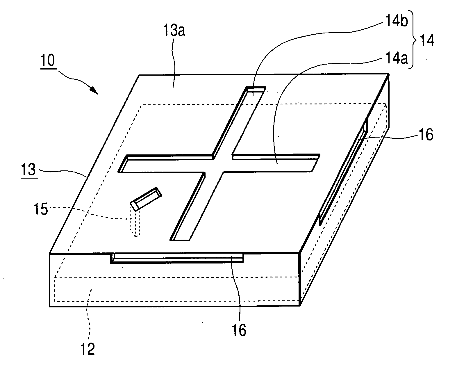
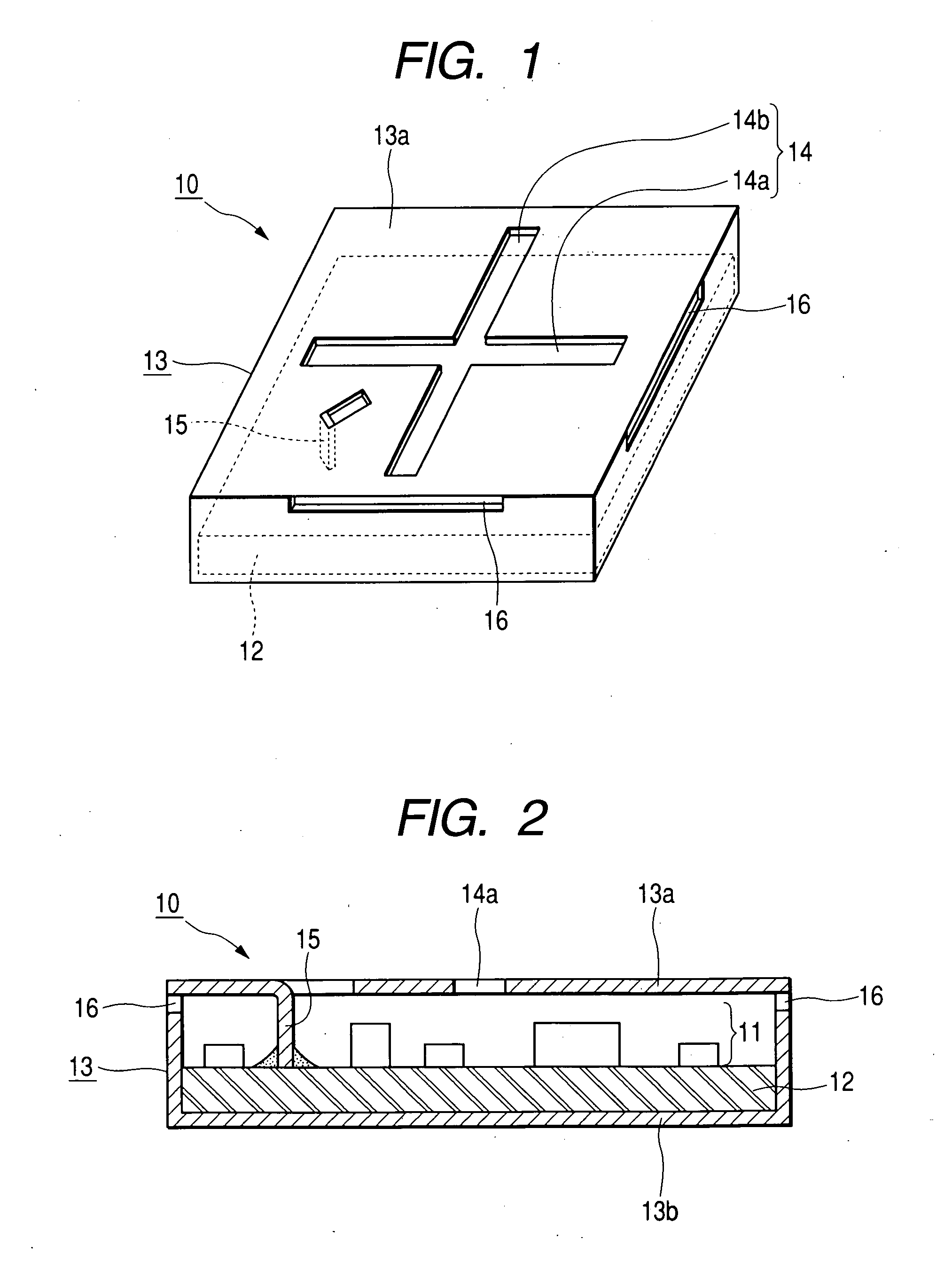
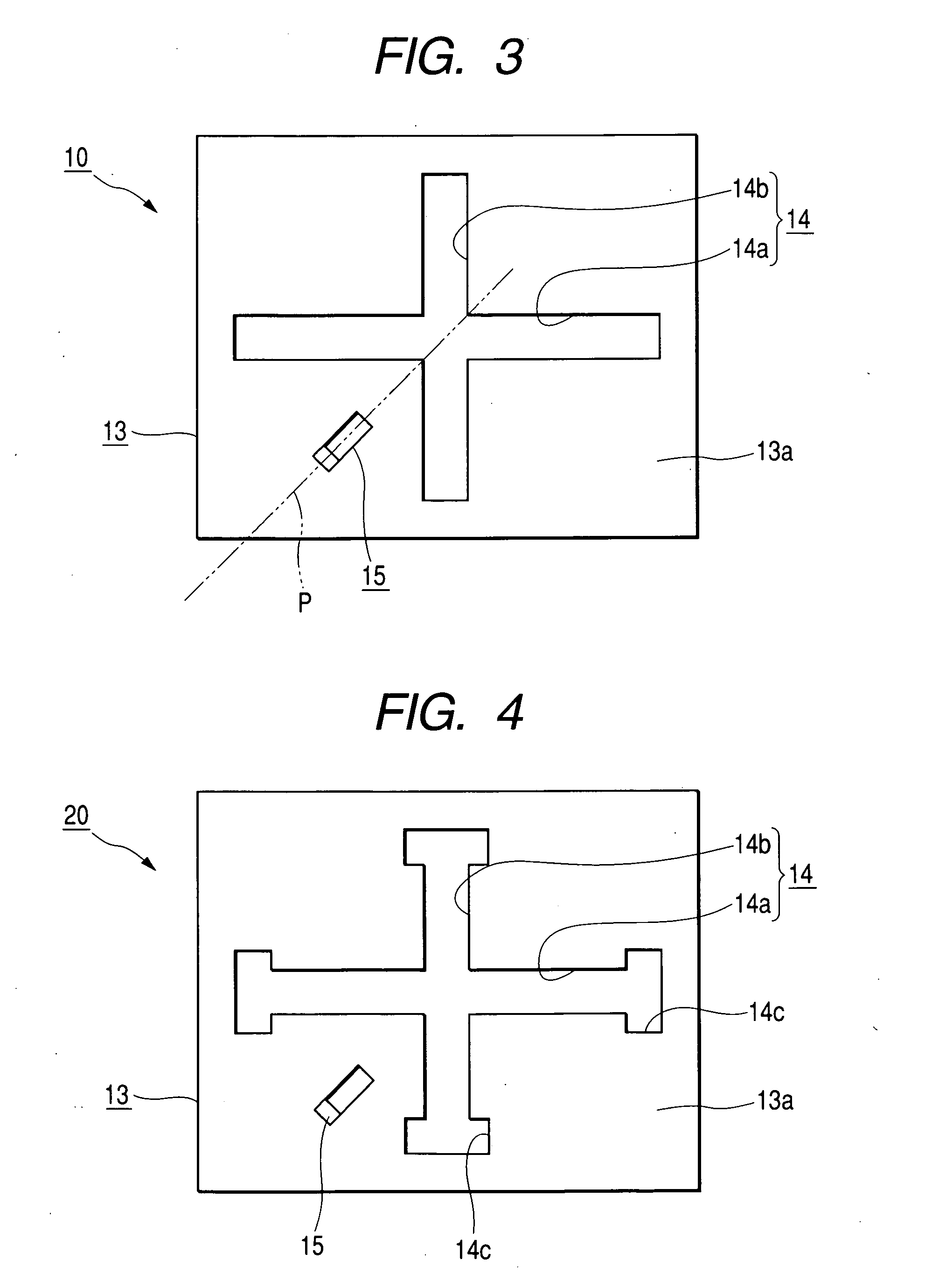
[0021] Hereinafter, embodiments of the present invention will now be described with reference to the accompanying drawings. FIG. 1 is a perspective view of a slot antenna apparatus according to a first embodiment of the present invention, FIG. 2 is a sectional view of the slot antenna apparatus according to the first embodiment of the present invention, and FIG. 3 is a plan view of the slot antenna apparatus according to the first embodiment of the present invention.

[0022] As shown in FIGS. 1 to 3, the slot antenna apparatus 10 comprises a circuit substrate 12 in which a high-frequency circuit 11 including as an amplifier, an oscillator or the like is arranged and a shield case 13 which is a case body accommodating the circuit substrate 12 and is composed of an excellent conductive metal plate. A cross-shaped slot 14 and a feeding pin 15 are formed in an upper plate 13a of the shield case 13. The cross-shaped slot 14 formed in the upper plate 13a is composed of a first slot 14a and...


PUM


Abstract

A slot antenna apparatus 10 contains a circuit substrate having a high-frequency circuit arranged therein and a shield case accommodating the circuit substrates. A cross-shaped slot and a feeding pin are formed in an upper plate of the shield case. The cross-shaped slot is composed of a first and second slots. The lengths of the slots are different and the slots are perpendicular to each other. The shortest distances from the feeding pin to the first slots are approximately equal. When the power is fed to the upper plate through the feeding pin, the slots are excited to irradiate linearly polarized waves perpendicular to each other, respectively.

Description

BACKGROUND OF THE INVENTION [0001] 1. Field of the Invention [0002] The present invention relates to a slot antenna apparatus, and more particularly, to a slot antenna apparatus which is operated as a circular polarization antenna. [0003] 2. Description of the Related Art [0004] A slot antenna apparatus comprises a conductor member composed of a metal foil or a metal plate in which a slot having a predetermined size is formed and a circuit substrate in which a high-frequency circuit including an amplifier, an oscillator or the like is arranged. By feeding a power to an appropriate location of the conductor member through a feeding means such as a feeding line connected to the circuit substrate, a slot is excited and a linearly polarized wave can be irradiated. As a conventional example of such a slot antenna apparatus, an antenna apparatus in which an antenna unit is provided at one side of the circuit substrate is widely known (for example, see Japanese unexamined Patent Applicatio...

Claims


Application Information

Patent Timeline
Patent Type & Authority Applications(United States)
IPC IPC(8): H01Q13/10H01Q13/18H01Q21/24
CPCH01Q13/10H01Q21/24H01Q13/18
Inventor YUANZHU, DOU
Owner ALPS ALPINE CO LTD
Learn More