
Toothbrush and process for producing the same

a technology for teeth and brushes, applied in the field of teeth brushes, can solve the problems of not being able to penetrate water or other foreign matter during the intended use of teeth brushing, and achieve the effect of reliable operation and cost-effectiveness

Active Publication Date: 2005-05-19
TRISA HLDG AG
View PDF8 Cites 10 Cited by
  • Summary
  • Abstract
  • Description
  • Claims
  • Application Information

AI Technical Summary

Benefits of technology

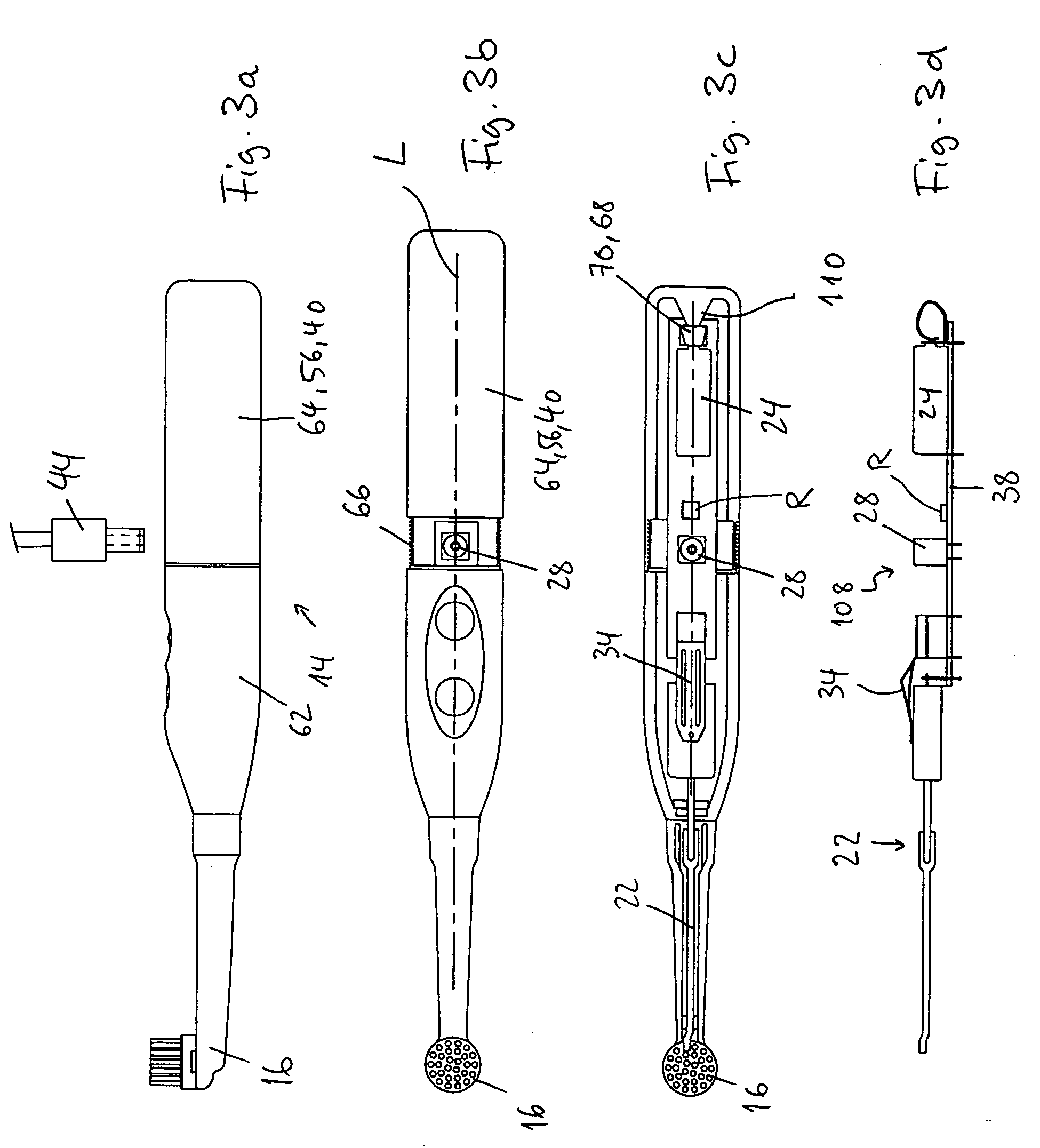
[0006] An aspect of the invention is to develop a cost-effective charging method which allows reliable operation, can be used in a space-saving manner, is as straightforward as possible to implement and allows minimal dimensions of the electric toothbrush.
[0007] The direct loading method for electrical equipment, e.g., mobile telephones, which is known per se, is adapted according to aspects of the invention such that it can also be used for toothbrushes having electrical functional components in the wet region. The charging current is transmitted to the electric toothbrush directly, i.e., by contact elements, using a power supply unit comprising a transformer and rectifying element or comprising a clocked electronic circuit. Provided within the toothbrush, instead of a costly charging circuit which takes up a lot of space, is just one contact element, if appropriate, with connecting lines to the storage battery. The toothbrush may thus be configured to be considerably more slender and lightweight than conventional electric toothbrushes with inductive charging and is easier to handle. For the purpose of fulfilling aesthetic requirements, there is more design freedom. The invention makes it possible to use favorable, mass-produced components, possibly standard elements, and thus power supply units which are already present in the home.
[0008] According to the invention, the inner space of the toothbrush, in which the energy store is located, is sealed by a primary sealing element, with the result that it is not possible for any water or other foreign matter to penetrate during intended use of the toothbrush. This prevents corrosion and contamination of the energy store and of the electrical contacts.

Problems solved by technology

According to the invention, the inner space of the toothbrush, in which the energy store is located, is sealed by a primary sealing element, with the result that it is not possible for any water or other foreign matter to penetrate during intended use of the toothbrush.

Method used


Image

  • Toothbrush and process for producing the same
  • Toothbrush and process for producing the same
  • Toothbrush and process for producing the same

Examples


case 1

[0111] Case 1: the contact element 28, together with the energy store 24, is located in the inner space 36, which is closed off with sealing action by a closure 40 (FIGS. 1 and 3-5). During normal operation (FIG. 12a), the primary sealing element (closure 40) closes off the inner space 36 in a water-tight manner. A switch 70, which is actuated by placing the closure 40 in position / removing the closure 40, is closed. The user can switch the consumer 22 on and off by a further switch 34. If the closure 40 is removed, the switch 70 inevitably switches off the connection between the storage battery 24 and the consumer 22 (FIG. 12b). In the open, i.e. non-sealed state, it is thus no longer possible for the electric toothbrush to be switched on. During charging of the storage battery 24 by virtue of the plug 44 being plugged into the socket 28, the inner space 36 is open (FIG. 12c). By providing the switch 70, it is then additionally possible to achieve the situation where charging of the...

case 2 (figs.12d-e) : the inner space 36 is completely sealed in relation to the contact element 28 in each operating state (figs.7-10).since the primary seal is not removed , a distinction is only made between two operating states , to be precise , the normal operating state (fig.12d) and the charging state (fig.12e).the operation of opening or closing the secondary seal need not , in fact , have any influence on the charging circuit.for the purpose of charging the storage battery 24 , the socket 28 preferably has an integrated switch 70 which performs the task of the switch 70 actuated by the closure in case 1.this integrated switch 70 guarantees that the storage battery 24 can be charged irrespective of the switching state of the switch 34.the integrated switch 70 is opened when the plug 44 is plugged in (fig.12e)

[0112] Case 2 (FIGS. 12d-e): the inner space 36 is completely sealed in relation to the contact element 28 in each operating state (FIGS. 7-10). Since the primary seal is not removed, a distinction is only made between two operating states, to be precise, the normal operating state (FIG. 12d) and the charging state (FIG. 12e). The operation of opening or closing the secondary seal need not, in fact, have any influence on the charging circuit. For the purpose of charging the storage battery 24, the socket 28 preferably has an integrated switch 70 which performs the task of the switch 70 actuated by the closure in case 1. This integrated switch 70 guarantees that the storage battery 24 can be charged irrespective of the switching state of the switch 34. The integrated switch 70 is opened when the plug 44 is plugged in (FIG. 12e), and thus prevents the situation where a completely empty storage battery 24 cannot be charged because the consumer 22 is connected to the storage battery 24 ...

case 3 (figs.12f-h)

[0114] Case 3 (FIGS. 12f-h): in a manner analogous to case 1, a distinction is made here, once again, between three operating states. The switch 70 corresponds to the spring element 72 shown in FIG. 6, and the switch 70′, as in case 2, is preferably integrated in the contact element 28.

[0115]FIG. 12f describes the normal operating state. The user switches the consumer 22 on and off via the switch 34. The switches 70 (actuated by the closure) and 70′ (integrated in the contact element 28) are closed. The resistor R is short-circuited by the closed switch 70.

[0116]FIG. 12g describes the state in which the closure has been removed and the consumer, irrespective of the state of the switch 34, on account of the risk of contamination, is not to function. In this operating state, it is indeed the case that the consumer 22 is in electrical connection with the storage battery 24 via the resistor R, but it will nevertheless not be possible to switch it on, since the resistance of the resisto...


PUM


Abstract

An electric toothbrush includes a rechargeable energy store which is arranged in an inner space in the body of the toothbrush. The inner space is sealed by a primary sealing element against splash water and other detrimental influences. At least one contact element for an external power supply unit produces an electrically conductive connection to the energy store. The contact element is located either within the inner space, the primary sealing element being removable for charging purposes, or outside the inner space, in which case it is optionally protected by an additional secondary sealing element. The invention also relates to a process for producing such a toothbrush.

Description

BACKGROUND OF THE INVENTION [0001] 1. Field of Invention [0002] The invention relates to a toothbrush having an electrically operated functional unit and an electrical supply device and to a process for producing such a toothbrush. [0003] 2. Description of Related Art [0004] Electric toothbrushes with rechargeable energy stores (storage batteries) are known and widely available on the market. In most cases, electrical energy is transmitted inductively to the energy store from the charging station. This is described, for example, in CH 656 987. Since there is no need for any electrical line connections between the energy store and the charging station, the advantage of this charging method resides in the straightforward handling for the user (i.e., straightforward positioning in the charging station without trying to find contact) and in the low level of susceptibility to external influences, e.g., water or toothpaste, which may result in contamination or corrosion of electrical cont...

Claims


Application Information

Patent Timeline
Patent Type & Authority Applications(United States)
IPC IPC(8): A61C17/22A61C17/26A61C17/34
CPCA61C17/224A61C17/22
Inventor PFENNIGER, PHILIPPPFENNIGER, ADRIANFISCHER, FRANZ
Owner TRISA HLDG AG
Learn More