
Modular laboratory cabinet

a laboratory cabinet and module technology, applied in the field of laboratory equipment, can solve the problems of cumbersome and expensive transportation and storage of fixed size laboratory cabinets, and inconvenient adjustment of holding capacity, so as to facilitate the adjustment of holding capacity. , the effect of simple configuration

Inactive Publication Date: 2005-05-19
BEL ART PRODS
View PDF30 Cites 15 Cited by
  • Summary
  • Abstract
  • Description
  • Claims
  • Application Information

AI Technical Summary

Benefits of technology

"The invention is a modular cabinet assembly designed for laboratory applications. It has a simple design that allows users to easily adjust its holding capacity and orientation. The cabinet consists of two housing end units and a base module arranged in an inverted spaced apart relation to each other. The housing end units have elongated supporting members with apertures passing through them, while the base module has a recessed area on its engaging peripheral edge. An intermediate housing module is interposed between each housing end unit and the base module, with front side portions that form a continuous opening adapted to accommodate a door. The technical effect of this invention is a versatile and customizable modular cabinet assembly that can be easily adapted to different laboratory needs."

Problems solved by technology

Furthermore, fixed size laboratory cabinets are quite bulky, as a result, their shipment and storage can be cumbersome and expensive.
Consequently, it is well known that there are inherent inefficiencies associated with fixed size laboratory cabinets.
However, these known storage devices generally suffer from one or more drawbacks and limitations which render them undesirable for the aforementioned laboratory applications.
However, the modular cabinet design disclosed in the '459 patent does not provide an airtight compartment.
Furthermore, the design requirements of the particular application, i.e., holding heavy electrical equipment, result in a storage unit having a relatively complex structure incorporating numerous individual components and necessitating at least some prefabrication prior to shipment to an end user.
Moreover, the disclosed cabinet has a metal construction that is undesirable for many laboratory applications including, for example, storage of certain chemicals.
However, these disclosed exemplary devices suffer from one or more of the aforementioned drawbacks and limitations, rendering them inconvenient / unacceptable for use for various laboratory applications.

Method used


Image

  • Modular laboratory cabinet
  • Modular laboratory cabinet
  • Modular laboratory cabinet

Examples


Embodiment Construction

[0040] Shown throughout the figures, the present invention is generally directed to an insulated modular cabinet assembly adapted for use in various laboratory environments. The assembly incorporates a simple and flexible stackable modular design lending itself to effortless on-site assembly and customization by an end user.

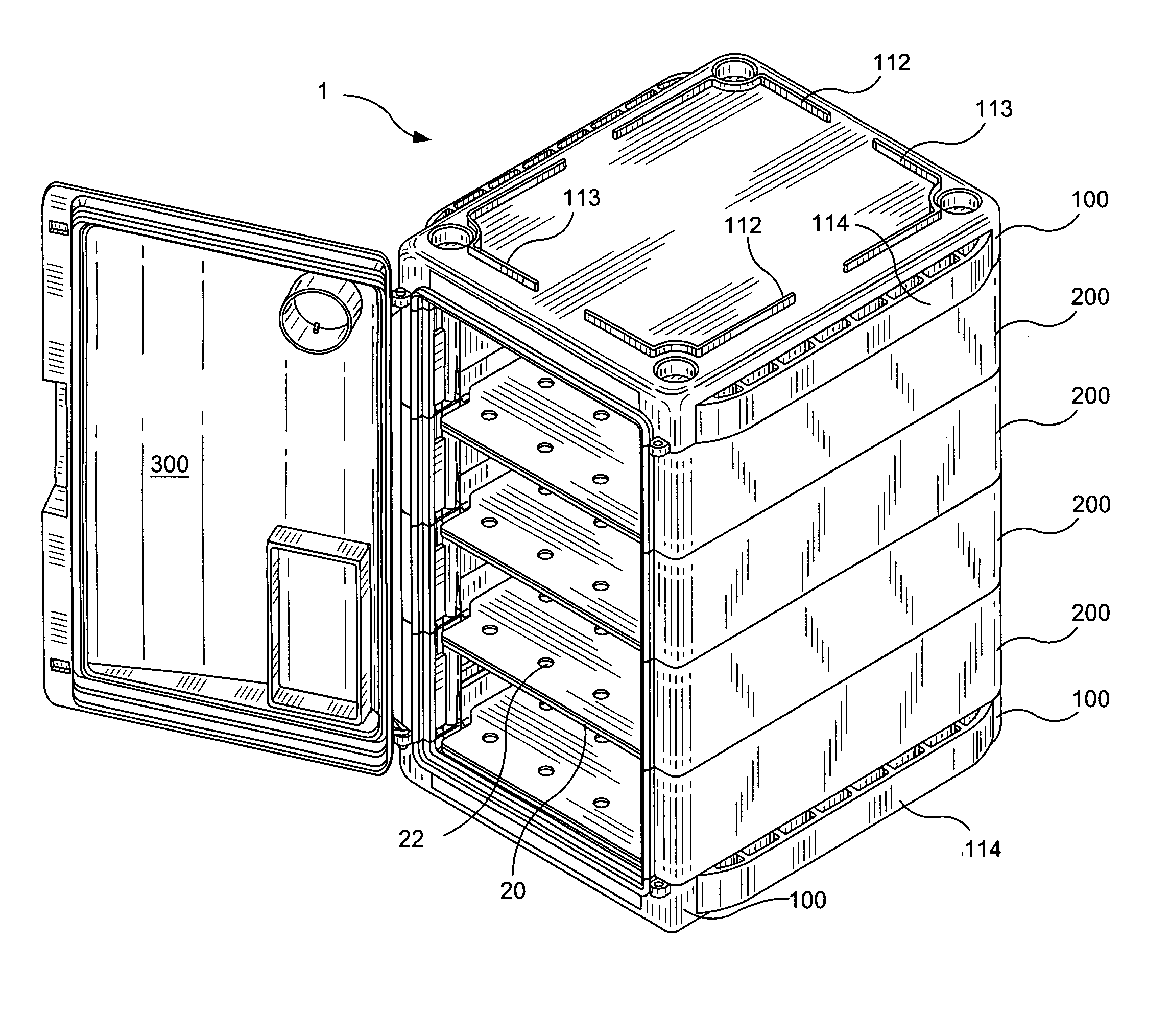
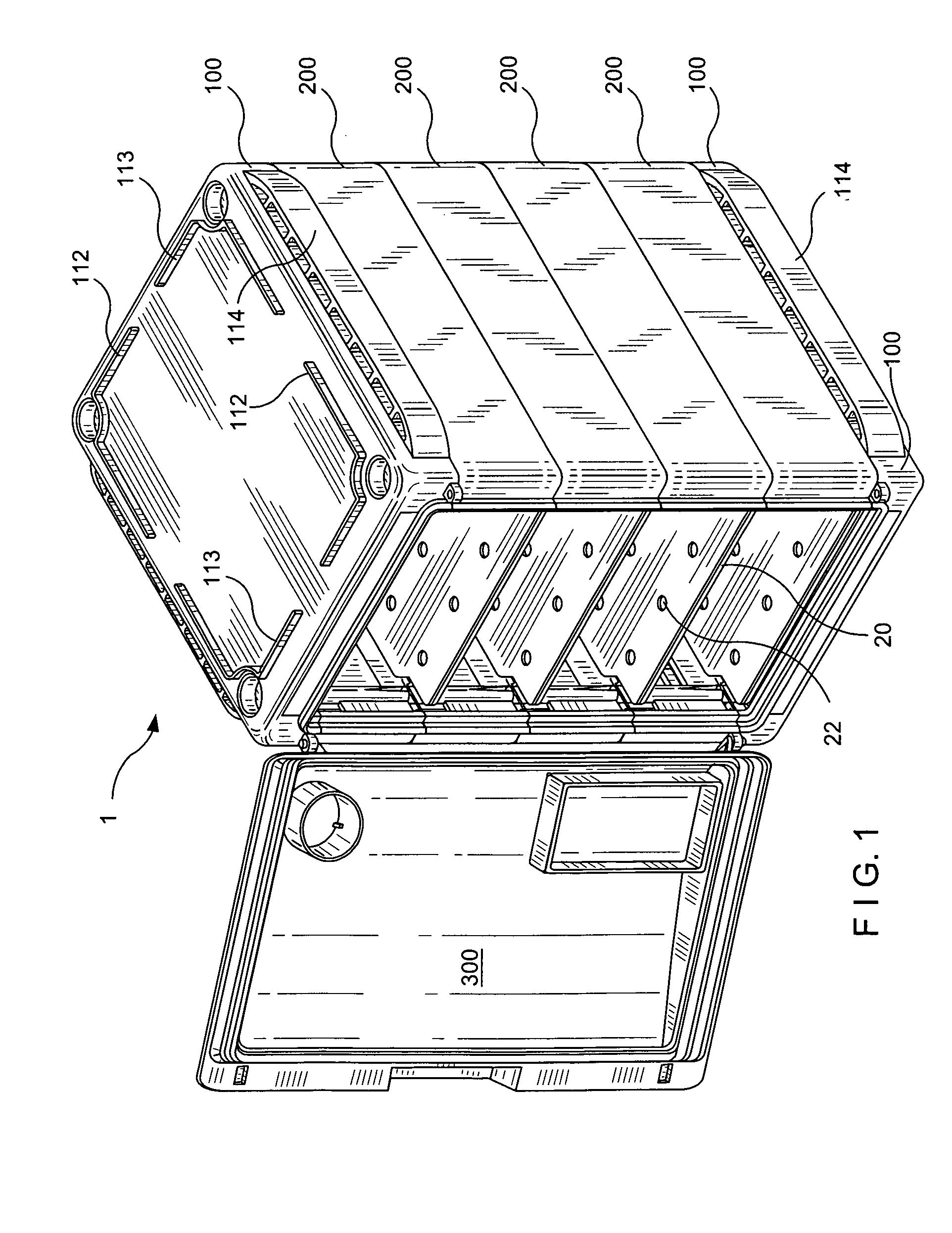
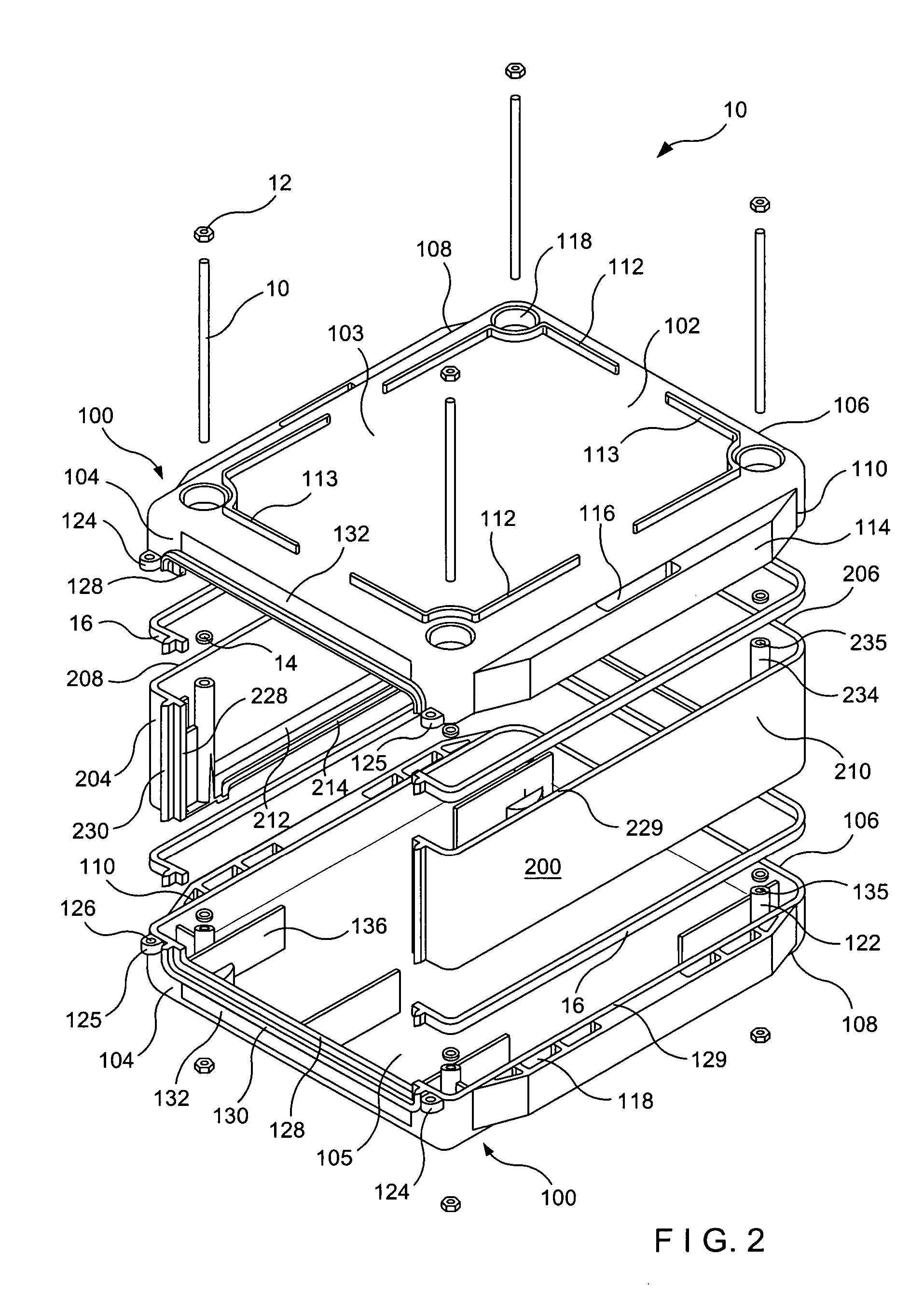
[0041] Referring initially to FIG. 1, a preferred embodiment of the modular cabinet assembly 1 of the present invention is illustrated in a fully assembled state. The modular cabinet assembly 1 generally includes a housing subassembly comprised of one or more stackable modules 200 interposed between a pair of identical opposing housing end units 100, and a cabinet door 300 hingedly connected to the front of the housing end units 100. As will be described in more detail below, the housing end units 100 and interposed stackable modules 200 are securely fastened to one another using fastening components, sealing gaskets and the like, such that in a completely assem...


PUM

PropertyMeasurementUnit
areaaaaaaaaaaa
recessed areaaaaaaaaaaa
relative humidityaaaaaaaaaa

Abstract

A modular laboratory cabinet assembly consists of a pair of identical housing end units arranged in an inverted spaced apart relations to each other, and at least a pair of identical base housing modules arranged in an inverted side by side relations to each other and interposed between the housing end units.

Description

[0001] This non-provisional application is a Continuation-in-Part Application of U.S. patent application Ser. No. 10 / 075,262 filed Feb. 15, 2002, currently pending, which claims benefit under 35 USC 119(e) of U.S. provisional application Ser. No. 60 / 273,871 filed by David Landsberger, Paul Thom and Francis Gomes on Mar. 7, 2001.BACKGROUND OF THE INVENTION [0002] 1. Field of the Invention [0003] The present invention relates generally to a laboratory equipment and, more particularly, to a modular laboratory cabinet assembly enabling an end user to tailor the cabinet holding capacity and the cabinet orientation on a supporting surface. [0004] 2. Description of the Prior Art [0005] Cabinets are commonly used in laboratories to accommodate various types of laboratory related equipment, as well as to accommodate products, materials, substances and the like during processing and testing. For many laboratory related applications it is desirable, or even necessary, to use such device having...

Claims


Application Information

Patent Timeline
Patent Type & Authority Applications(United States)
IPC IPC(8): A47B47/04A47B47/00A47B87/02B01L1/02B65D6/02B65D21/02B65D21/08
CPCA47B47/0091B01L1/02A47B87/02A47B47/00
Inventor LANDSBERGER, DAVIDTHOM, PAULGOMES, FRANCIS
Owner BEL ART PRODS
Learn More