
Adhesive wheel balancing weights having a serrated backing strip

a technology of backing strip and adhesive wheel, which is applied in the direction of rotating body balancing, mechanical equipment, transportation and packaging, etc., can solve the problems of clip weights and potentially damaging wheels, contact between two dissimilar metals, and potential corrosion, so as to facilitate the separation of individual weights quickly and easily, and the effect of easing the removal of backing strip

Inactive Publication Date: 2005-05-19
HALKO MFG
View PDF42 Cites 32 Cited by
  • Summary
  • Abstract
  • Description
  • Claims
  • Application Information

AI Technical Summary

Benefits of technology

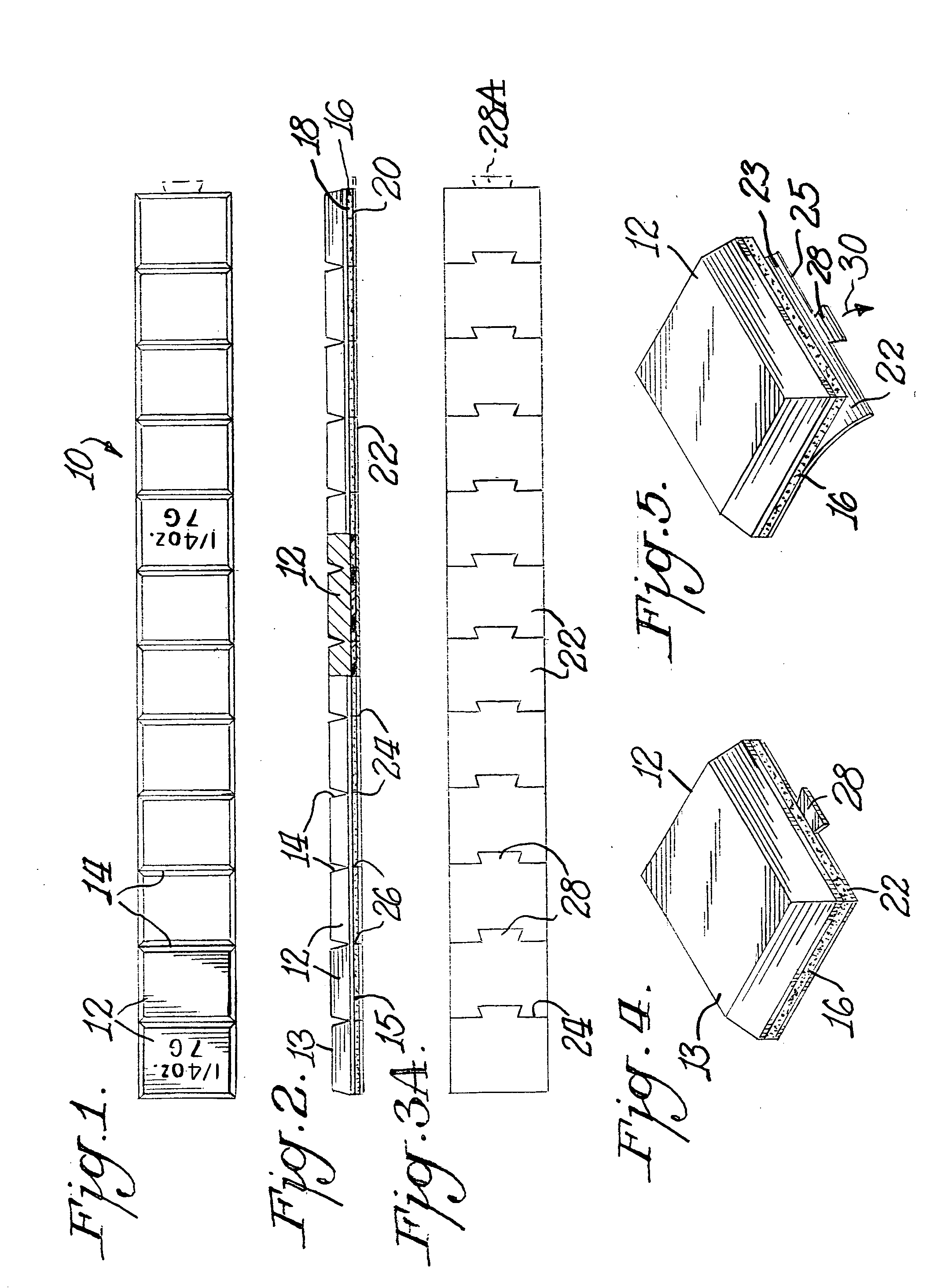
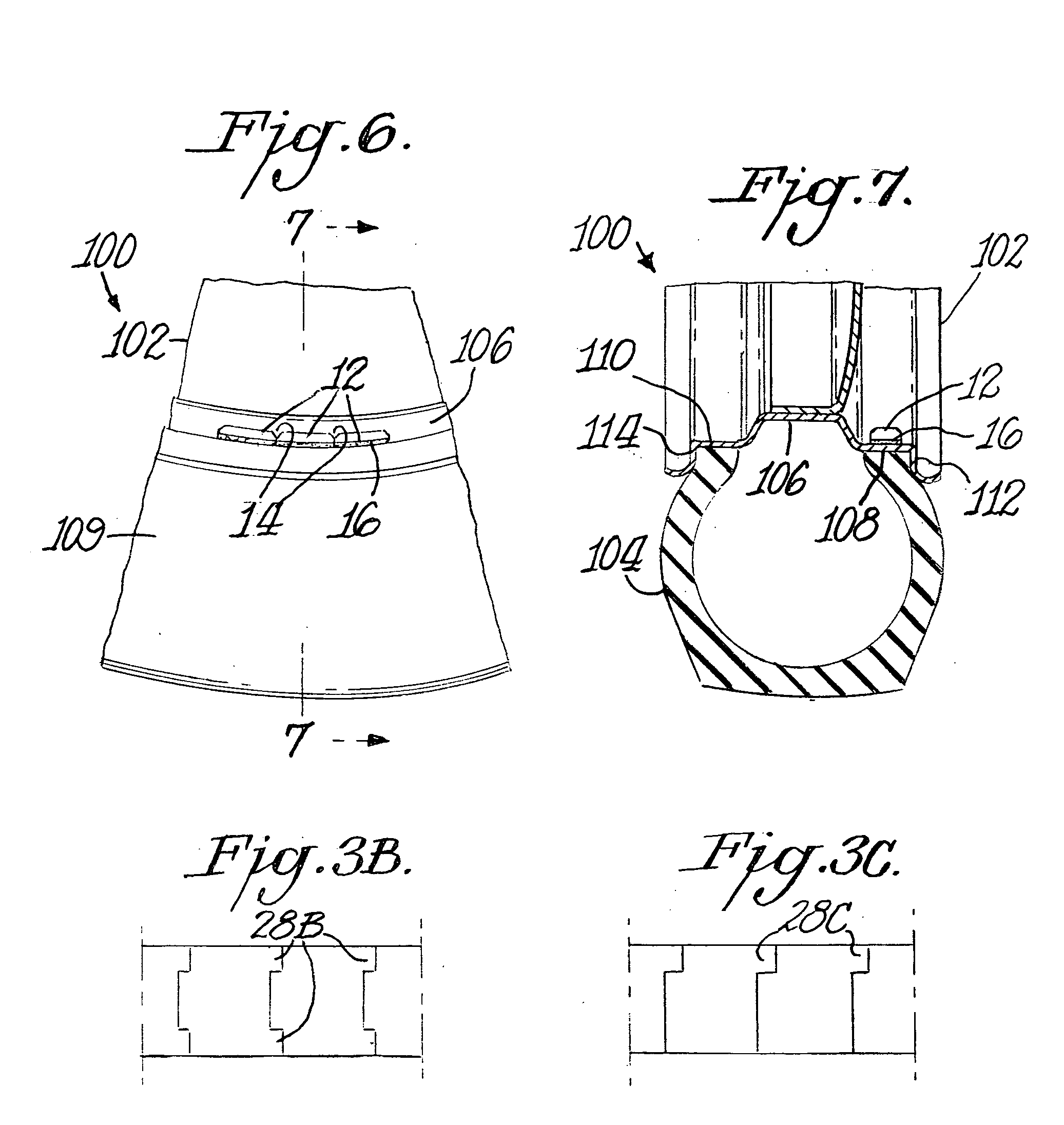
[0011] The present invention solves the problems of the related art by providing a wheel balancing device having a plurality of wheel balancing weights attached to a top surface of an elongate tape, and a backing strip removably attached to and protecting an adhesive layer on the bottom surface of the tape. The backing strip is serrated below the grooves separating the individual wheel balancing weights to facilitate separation of the individual weights quickly and easily. Each backing strip serration may be in the shape of a lift tab or finger grip to further ease removal of the backing strip from the adhesive layer on the bottom surface of the tape.
[0012] The wheel balancing device of the present invention eliminates the need for an additional cutting tool to sever the backing strip when individual weights or groups of weights are manually separated from the wheel balancing device. The wheel balancing device also prevents contamination of adjacent adhesive layers of non-separated weights, eliminating waste of unused wheel balancing weights.

Problems solved by technology

Such clip weights, as they are known, however, result in the contact of two dissimilar metals (that is the steel clip and the rim).
In severe winter and salt driving conditions, which form electrolytes, the potential for corrosion exists due to the contact of these dissimilar metals.
Clip weights can also potentially damage wheels by inflicting scratches thereon.
Such scratches may become noticeable upon removal or relocation of the wheel weight.
However, it is difficult to remove the backing strip from the tape because the surface area of the backing strip is coextensive with the surface area of the tape, thereby making it extremely difficult to initially separate the backing strip from the tape.
A further problem with the backing strip, not addressed in U.S. Pat. No. 6,364,421, is that a plurality of wheel balancing weights (each weight conventionally weighing 0.25 ounces, or any other weight value) are typically provided in end-to-end relationship upon the elongate strip of tape.
The separation of the individual weights becomes a cumbersome and time consuming exercise.
Conventional wheel balancing device arrangements also promote waste.
If the backing strip is peeled away from underneath the individual weights that are to be separated, but also underneath weights that are not to be separated, the adhesive under the non-separated weights will be exposed to grease, dirt, and other debris commonly found on the hands of the applicator and in the storage facility or garage.
If the adhesive becomes contaminated with such grease, dirt, or debris, it will not adhere to the rim properly, and the non-separated weights will need to be discarded.

Method used


Image

  • Adhesive wheel balancing weights having a serrated backing strip
  • Adhesive wheel balancing weights having a serrated backing strip
  • Adhesive wheel balancing weights having a serrated backing strip

Examples


Embodiment Construction

[0024] The following detailed description of the invention refers to the accompanying drawings. The same reference numbers in different drawings identify the same or similar elements. Also, the following detailed description does not limit the invention. Instead, the scope of the invention is defined by the appended claims and equivalents thereof.

[0025] A wheel balancing device in accordance with an embodiment of the present invention is generally illustrated in FIGS. 1, 2, and 3A as reference numeral 10. Wheel balancing device 10 may have a plurality of wheel balancing weights 12 mounted in end-to-end relationship upon an elongate strip of tape 16. Each weight 12 includes a top surface 13 and a bottom surface 15. Although FIGS. 1, 2, and 3A show twelve wheel balancing weights 12, any number of weights 12 may be provided on a strip of tape 16 and used in wheel balancing device 10 of the present invention. Preferably, each weight 12 is substantially the same size and weight. For exa...


PUM


Abstract

Disclosed herein is a wheel balancing device having a plurality of wheel balancing weights attached to a top surface of an elongate tape, and a backing strip removably attached to and protecting an adhesive layer on the bottom surface of the tape. The backing strip is serrated below the grooves separating the individual wheel balancing weights to facilitate separation of the individual weights quickly and easily. Each backing strip serration may be in the shape of a lift tab or finger grip to further ease removal of the backing strip from the adhesive layer on the bottom surface of the tape.

Description

CLAIM FOR PRIORITY [0001] The present application claims priority of Disclosure Document No. 523251, filed Nov. 15, 2002, the disclosure of which being incorporated by reference herein in its entirety.BACKGROUND OF THE INVENTION [0002] A. Field of the Invention [0003] The present invention relates generally to wheel balancing devices, and, more particularly to adhesive wheel balancing weights having a serrated backing strip. [0004] B. Description of the Related Art [0005] A number of wheel weight attachment systems have been proposed and used to improve the balance of a rotating wheel having a conventional pneumatic tire mounted thereon. Thus, it is known to apply a counterbalancing weight to a rim of the wheel to compensate for the rotational imbalance of the pneumatic tire and rim assembly. [0006] Conventional counterbalancing weights include lead weights molded around a steel clip, which in turn is attached to a flange of the rim. Such a circumferentially extending weight is sele...

Claims


Application Information

Patent Timeline
IPC IPC(8): B60B1/00F16F15/32
CPCF16F15/328Y10T428/149Y10T428/1476
Inventor PETCHEL, LAWRENCE D.HALKO, ANDREW R.
Owner HALKO MFG
Learn More