
Pointing device operation modification program

a technology of operation modification and pointing device, applied in the direction of electric digital data processing, instruments, computing, etc., can solve the problems of not all application programs understand and respond to the scroll wheel signal, and all pointing devices have scroll wheels, so as to simplify many common user tasks

Active Publication Date: 2005-05-12
LENOVO PC INT
View PDF15 Cites 2 Cited by
  • Summary
  • Abstract
  • Description
  • Claims
  • Application Information

AI Technical Summary

Benefits of technology

[0006] The present invention, which meets the needs identified above, is an Operation Modification Program. The Operation Modification Program simplifies many common user tasks in a GUI environment by eliminating steps that a user would otherwise repeat many times. In particular, the invention eliminates the need for a user to press and release a pointing device button in order to accomplish common tasks. Instead, the invention allows a user to rely only on pointer movement to accomplish the same common tasks.
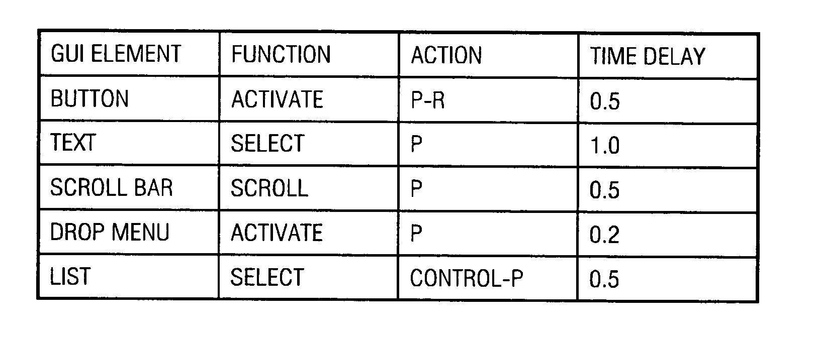
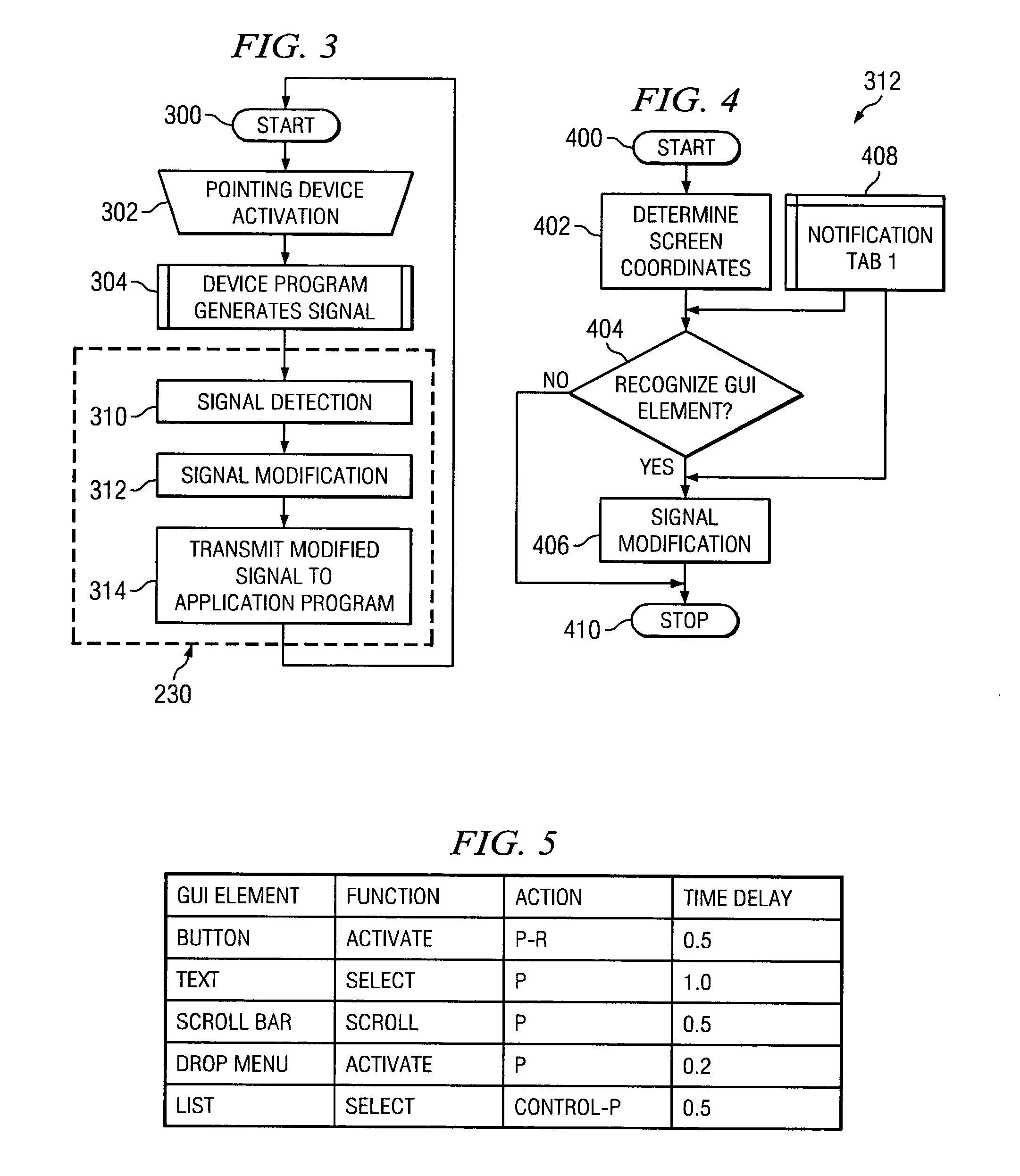
[0007] The Operation Modification Program (OPM) comprises a signal detector (SD), a signal modifier (SM), and a signal transmitter (ST). A pointing device generates signals whenever a user activates a pointing device. A pointing device program usually relays the pointing device signals to other application programs. An OPM, though, intercepts the pointing device signals before the application programs receive them. The SD continuously listens for signals generated by a pointing device, or a pointing device program. If the SD detects a pointing device signal, the SM determines what type of GUI element is located at the current pointer location. Based upon the identified GUI element, the SM modifies the pointing device signal appropriately. The ST then transmits the modified signal to any other programs that would have received the original signal, if not for the OPM action. For example, an OPM would eliminate the need for a user to press and release a pointing device button to activate a command button. Instead, a user would only be required to move the pointer over the command button. The OPM would recognize the placement over the command button and generate the press and release signals for the user. An OPM can be applied to many common tasks, including activating, selecting, scrolling, and sorting tasks. In an alternative embodiment, the Operation Modification Program would allow a user to customize the types of GUI elements recognized and the behavior applied to the recognized elements.

Problems solved by technology

But not all pointing devices have scroll wheels.
Furthermore, not all application programs understand and respond to the scroll wheel signal.

Method used


Image

  • Pointing device operation modification program
  • Pointing device operation modification program
  • Pointing device operation modification program

Examples


Embodiment Construction

[0014] As used herein, the term “activate” means any action that causes a pointing device to generate a signal, including without limitation moving the device, pressing a device button, and releasing a device button.

[0015] The term “command button” means any graphic element in a display that may be activated and that upon activation causes the computer to perform an action.

[0016] The term “device button” refers to a physical button on a user input device.

[0017] The term “device program” means any computer program that provides support and control to a specific hardware component, such as a pointing device, thereby allowing other programs to use the specific hardware component.

[0018] The term “graphic element” or “GUI element” includes without limitation graphic characters, objects, and images.

[0019] The term “hardware” includes any physical equipment in a computer system, such as a central processing unit (CPU), input devices, and output devices.

[0020] The term “operating syst...


PUM


Abstract

An apparatus and method for modifying and improving pointing device operation. The apparatus comprises a signal detector, a signal modifier, and a signal transmitter. The apparatus intercepts pointing device signals before application programs receive them. The signal detector continuously listens for signals generated by a pointing device, or a pointing device program. Responsive to the signal detector detecting a pointing device signal, the signal modifier determines what type of GUI element is located at the current pointer location. Based upon the identified GUI element, the signal modifier modifies the pointing device signal appropriately. The signal transmitter then relays the modified signal to any other programs that would have received the original signal if not for the action of the apparatus.

Description

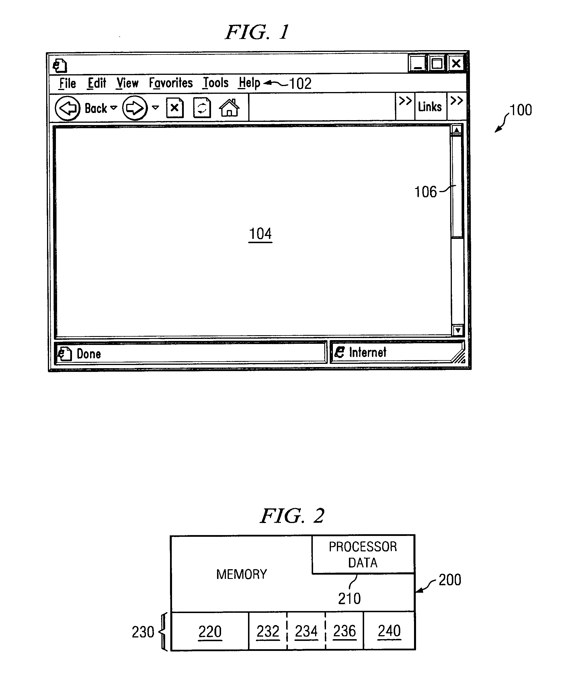
FIELD OF THE INVENTION [0001] The present invention relates to an apparatus for interacting with the graphical user interface of a computer, and more particularly to an improved method for using a pointing device to interact with a graphical user interface. BACKGROUND OF THE INVENTION [0002] Today, many computer users interact with a computer system through a graphical user interface. A graphical user interface (GUI) is a generic term for a collection of graphical elements displayed on a computer screen. To an end-user, the look and feel of different GUIs may be quite different, but almost all GUIs share some common elements. For instance, most GUIs use windows to organize the on-screen display. 0 is an illustration of a typical GUI window. Referring to 0 for illustration purposes, window 100 typically will have many common sub-elements, including menu interface 102. Other common window sub-elements include scroll bar 104 and scroll arrows 106, which allow a user to pan the informat...

Claims


Application Information

Patent Timeline
Patent Type & Authority Applications(United States)
IPC IPC(8): G06F3/033G06F3/048
CPCG06F3/04812
Inventor CHEN, YEN-FUWANG, RAYMOND TANG
Owner LENOVO PC INT
Learn More