
Electronic wireless locking system

a wireless locking and wireless technology, applied in the field of electronic wireless locking systems, can solve the problems of chain breaking, cheap locks negating the security effectiveness of all high-quality locks, and people needing access to facilities, etc., and achieve the effect of high volume usag

Inactive Publication Date: 2005-05-12
CHILDRESS ROBERT NEY +1
View PDF17 Cites 103 Cited by
  • Summary
  • Abstract
  • Description
  • Claims
  • Application Information

AI Technical Summary

Benefits of technology

[0015] One advantage of the invention is that, since communications are directed through a regular cellular telephone, there is no need to supply workers with special equipment, special phones, or other expensive gadgetry. Also, with cellular telephones and the cellular telephone links, there are no governmental regulatory requirements, permissions or licenses believed to be required since those are already inherent in the use of a cell phone.
[0016] An advantage to the disclosed system is that it accommodates the needs of company personnel and employees of allied companies who require immediate access to an enclosed, secure area secured with locking barriers, doors, gates, or the like. As this system is an automated system, largely controlled through a central computer system in a base station, the costs to manage the automated system will be insignificant as there are no routine service requirements. Components of the remote systems may be damaged from use or from malicious vandalism, but the inventor contemplates that the mechanical components of the system will be comparable in toughness to security padlock systems.
[0017] Another feature and advantage of this invention is that the base station, which needs to be accessed each time a lock module is cycled, is configured to maintain records of barrier and lock module activity. Thus the base station software will have records of barrier and lock module activity, including at least, who, what, when, why, and where each time a lock module or barrier is accessed. Interpretation of the records would aid management and subscribers in knowing the status of a particular secure location, that is, warnings or reminders to supervisors or security and liability managers, that some barriers are still open and have not yet been re-secured. In this scenario the safety of the worker can be considered; i.e., has too much time passed since the worker entered the secured area (indicating a problem), has the worker not exited the site at a proper time, has a gate, door, or other portal cover been left open because the worker is incapacitated in a health risk area, is the worker injured at the site, has the worker gotten lost, has the worker lost his ability to communicate by cell phone, etc. Also if an authorized entrant leaves a secured area without re-securing the barrier or lock related to a particular locking module, the entrant, or his company could be charged a fee to have an attendant re-secure the barrier. These records could be one method of doing business wherein a subscription fee would be charged for lock module customers or users, that is, a fee could be charged for keeping the records, reporting the data, and interpreting the data to assist customers in auditing access to a particular locked secure location. The records could be used for billing purposes as well. For instance, a fee could be charged based on usage of the lock module, however that is primarily an option where there is high volume usage by various individuals, such as real estate agents, accessing keys through a lock box. Another instance is the use of determining work time on the job, that is, the “on-the-dock” time a worker spends on a particular job. This could be the basis for billing for performing a particular job. One more instance of a record keeping function is the reporting of when a worker was at a particular location, similar to a security officer using a location specific key to trigger a record on the recording device he carries from location to location.
[0018] Another advantage of this invention is that workers will not be allowed to open a locked module, or a secured barrier, on their own, without first getting authorization from the base station.
[0019] This invention requires few service personnel to run effectively. Few, if any, special tools are needed. In most cases, workers already carry the tools they need to operate the lock module, such tools as a cell phone or a satellite phone and, where fold-out drive handles or locally stored handles are not provided, standard hand wrenches, a socket set for instance, are all that is needed.
[0020] Another advantage of the invention is that the locking module is a simply constructed device with few moving parts, no batteries to run low, no need for an external source of power which is a consideration where wiring and the possibility of short circuits presents an explosion or shock hazard.

Problems solved by technology

A related problem is that of emergency people needing access to a facility.
The cheap locks negate the security effectiveness of all the high quality locks.
Another problem associated with multiple locks connected together to form a chain situation is that if a company or person removes its lock from the chain, the chain is now broken as one link is removed and the custodian of an adjacent lock may not be available to hook his lock to the remain locks in the chain.
Another situation where conventional locks, such as padlocks and door locks are troublesome, is where the locks need to be changed periodically for security reasons.
Keys are also problematic in situations where access to a site is needed by a group of people where access is infrequent or revolving.
For instance, in a military environment where access to a site is restricted to a class or group of soldiers, it is inefficient to give a key to each soldier.
A weakness of this system is that the access code has to be taught to the potential entrant, remembered by the entrant, and not shared with others.
Also, keypad entry strokes can be observed, or recorded by unauthorized parties for eventual compromise of the secured portal.
Range on these devices is generally limited, however they do have the programmed capability of changing the access code after each activation.
Of course, there is no operator identification normally programmed in these devices.

Method used


Image

  • Electronic wireless locking system
  • Electronic wireless locking system
  • Electronic wireless locking system

Examples


Embodiment Construction

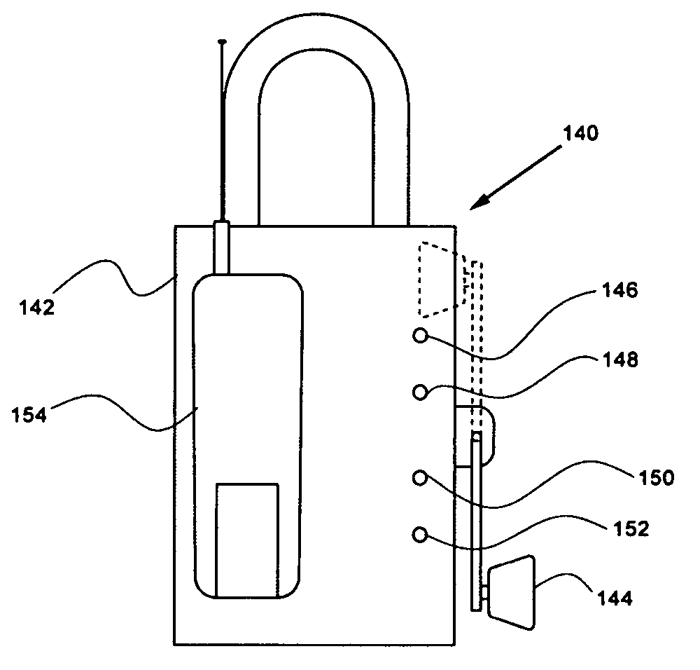
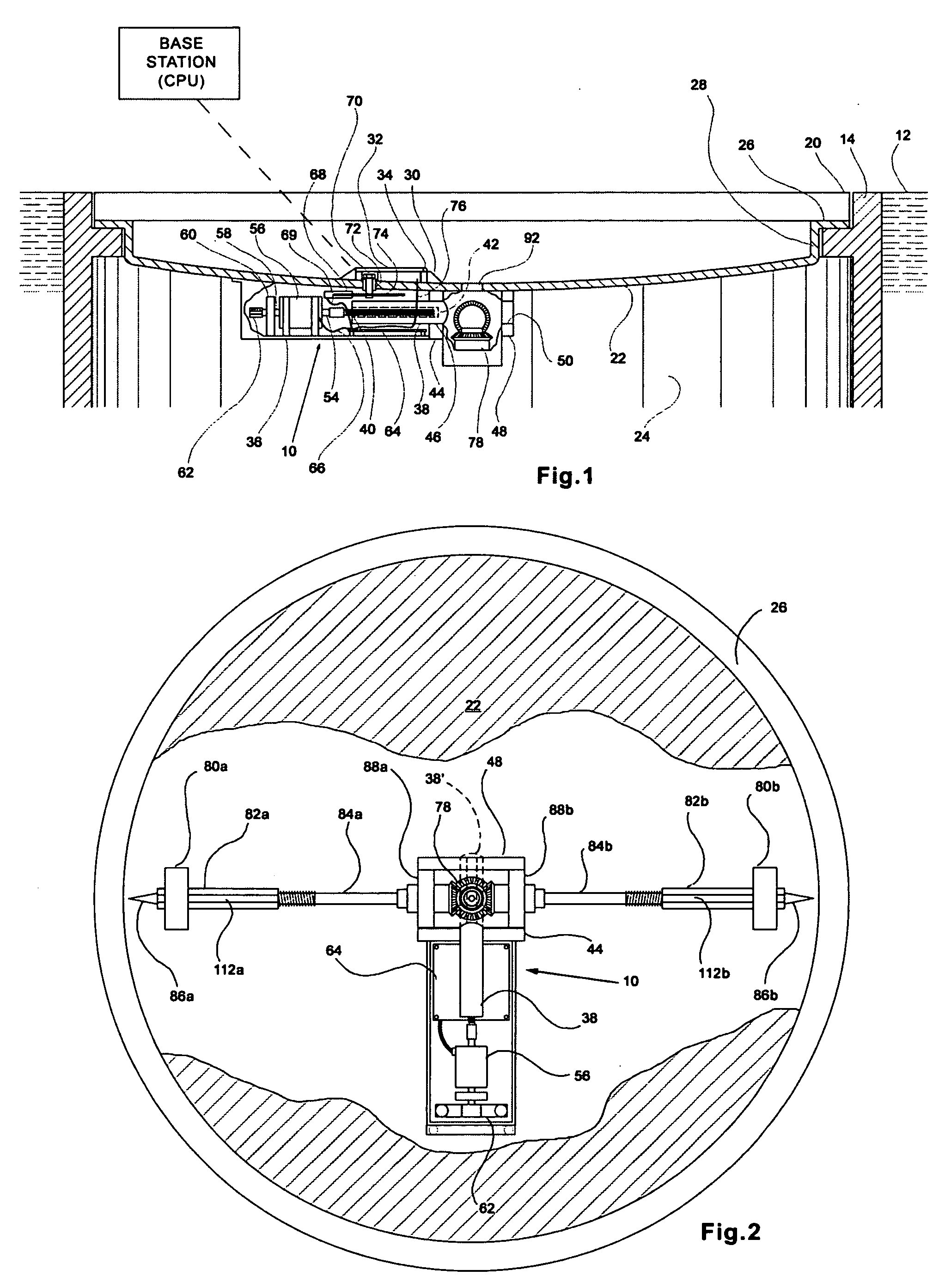
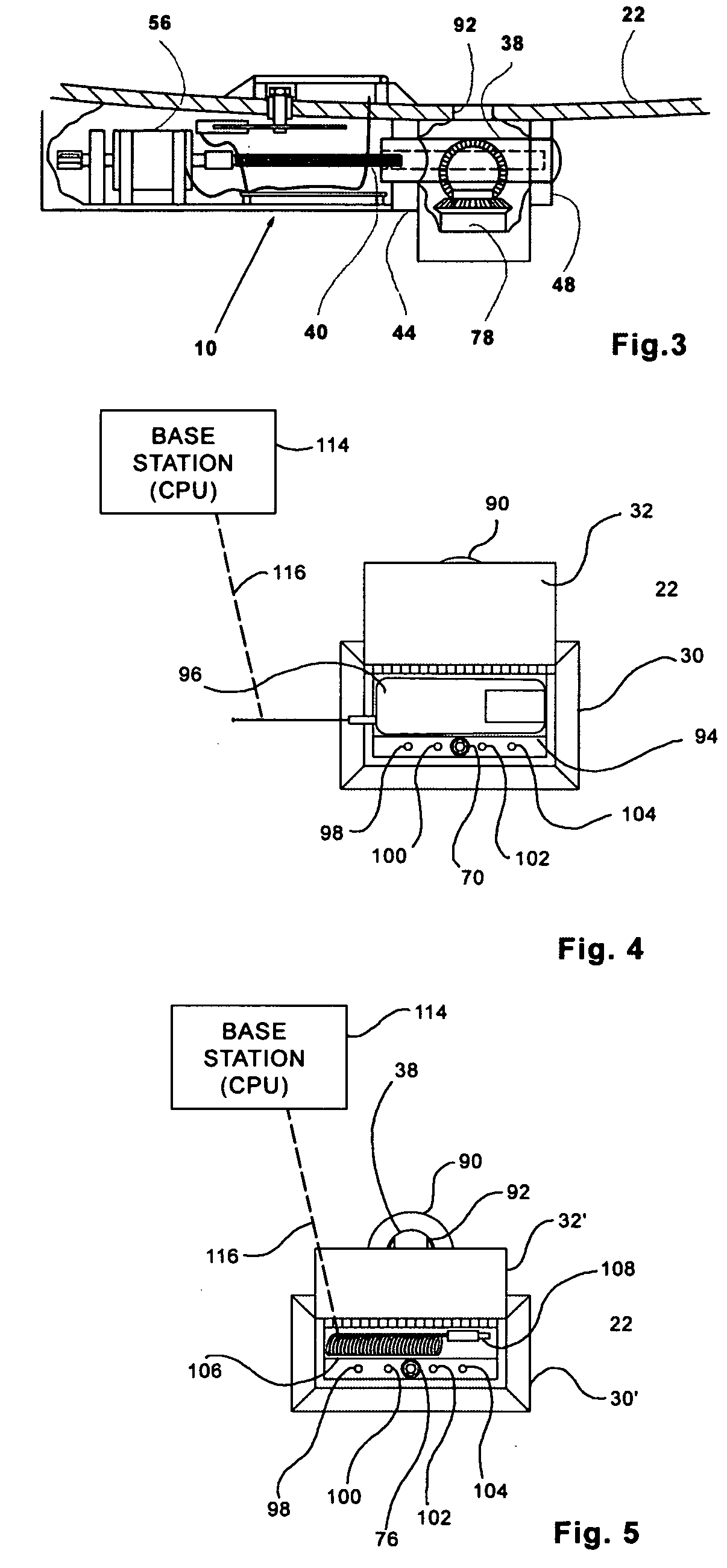
[0035] The invention is capable of numerous iterations and applications. One embodiment of the invention will be focused on to make the reader aware of the general principles of the invention. A perusal of the drawing figures while carefully reading this specification will provide the reader with an appreciation of the embodiments described, as well as embodiments that are logical extensions of those set forth herein.

[0036] The preferred embodiments of the invention presented here are described below in the drawing figures and Detailed Description of the Drawings. Unless specifically noted, it is intended that the words and phrases in the specification and the claims be given the ordinary and accustomed meaning to those of ordinary skill in the applicable arts. If any other special meaning is intended for any word or phrase, the specification will clearly state and define the special meaning.

[0037] Beginning with FIG. 1, an overview of one embodiment of the invention can be clearl...


PUM


Abstract

This invention pertains to the use of a cellular telephone to control a locking module. The locking module is used in controlling access to a secured location, a vehicle, or through a door, or other structure or situation where access is or may be controlled by use of a locking device. Cellular telephone communication links are used to communicate between a base station and a remote lock module such that activity at the remote location is controlled by the base station. Variations and methods with different advantageous features are also described.

Description

BACKGROUND OF THE INVENTION [0001] This invention relates to the use of a standard cellular telephone link to provide communications to and from a base station and a remote locking module. The locking module may be used as a mechanism that prevents access to a conventional lock assembly, controls access to a secured location, building, structure, outpost, lockup, chamber, passage or access port, fenced or walled area, lockbox, vehicle, vessel, aircraft, or through a door, gate, window, lid, drawer, or any other structure or situation where access is or may be controlled by use of a lock, latch, keyed, coded or triggerable locking device or the like. [0002] Access to secured locations is often controlled by use of locks that prevent the opening of access ports, doors or gates. The locks are usually keyed or combination-controlled locks where the lock will only opens when the proper key or combination is used. Coded locks, where a key code is input to a control module and the control ...

Claims


Application Information

Patent Timeline
Patent Type & Authority Applications(United States)
IPC IPC(8): G05B19/00G07C9/00
CPCG07C9/00103G07C9/00309G07C2009/00793G07C2009/00761G07C2009/00634G07C9/21G07C9/27
Inventor CHILDRESS, ROBERT NEYCLARK, GREG S.
Owner CHILDRESS ROBERT NEY
Learn More