Injection needle and injection apparatus

a technology which is applied in the field of injection needle and injection tube, can solve the problems of affecting the safety of patients, and difficult to assemble thin needles firmly to the base in the middle of the needle, etc., and achieves the effects of reducing patients' pain, convenient manufacturing, and sufficient strength

Inactive Publication Date: 2005-05-05
TERUMO KK
View PDF16 Cites 4 Cited by
  • Summary
  • Abstract
  • Description
  • Claims
  • Application Information

AI Technical Summary

Benefits of technology

[0018] The object of this invention is to provide an injection needle and an injection apparatus that are capable of reducing patients' pains, can be manufactured easily, and have a sufficient strength to penetrate rubber stoppers and a less injection resistance.
[0026] According to the injection needle of this invention, it is possible to make the puncture part of the needle that is capable of puncturing a body thinner than it used to be. Consequently, it is possible to reduce the area of the needle that contacts with the nerve net, minimize the attack on the nerve net, and alleviate the patient's pain.
[0027] Furthermore, the injection needle of this invention is not intended to affix the needle with a thin, constant diameter needle to the base at the middle of its length. Therefore, it is easy to assemble and manufacture the injection needle even though the puncturing part of the needle is thin.
[0028] As the cutting edge can be formed at the end of the liquid introducing needle part, which has a relatively thicker diameter, for penetrating the elastic member that is used to seal the liquid injection port of the liquid container, it can have a sufficient strength to penetrate through the elastic member. Consequently, it is possible to prevent a situation where the needle breaks and cannot penetrate though the elastic member.
[0029] Moreover, by thickening the liquid introducing needle part, the injection resistance can be reduced. Therefore, the force required for injecting the liquid drug can be reduced and the liquid drug can be injected into the body more ideally.
[0030] Consequently, the invention provides a thinner injection needle that causes no pain or extremely small pains and yet causes less injection resistance by making the part that punctures the patient's skin thinner and other parts of the needle relatively thicker. In particular, by setting the outer diameter of the puncturing part to be not more than 0.254 mm, or preferably in the range of 0.1-0.25 mm, or more preferably in the range of 0.18-0.22 mm, it is possible to have a puncturing part equal or thinner than the thinnest needle currently available on the market, and yet reduce the injection resistance simultaneously. Therefore, it is possible to provide an injection needle that is capable of administering liquid drugs quickly and easily even when it is operated by a patient who is physically or mentally weak such as a woman, child and an aged person.

Problems solved by technology

Therefore, it causes a pain when the needle 102 punctures a living body or when a liquid drug is injected into a living body.
The thought of puncturing with such a thick needle also causes fear or threat to patients.
Another problem is that it is extremely difficult to assemble a thin needle firmly to the base in the middle of the needle as shown in FIG. 2, if it is attempted to use a thinner needle in order to reduce the pains of patients.
Furthermore, such a thin needle tends to be too weak.
Therefore, the needle may not be able to penetrate through the rubber stopper provided on the drug injection port of the drug container and may end up breaking when it is attempted to install the needle on the drug container.
Moreover, such a thin needle inherently has a thin inner diameter so that its liquid path resistance during injection (“injection resistance”), aggravated by its relatively long length, becomes extremely large.
Thus, it has a problem that it requires a substantially large force to push out the liquid drug during injection.
This makes it difficult for a person, who is a physically or mentally weak patient and doesn't have a sufficient force to push the plunger of the drug injection apparatus, such as a woman, child or an aged person, to inject liquid drugs subcutaneously using needles with an outer diameter of 0.254 mm (31 G).
Overflowing of the liquid drug after injection means that less than the specified amount of the liquid drug is administered and that the treatment is not sufficiently performed.
As can be seen from the above, it has been impossible to reduce the outer diameter of the needle to alleviate the patient's pain because of those problems mentioned above.

Method used


Image

  • Injection needle and injection apparatus
  • Injection needle and injection apparatus
  • Injection needle and injection apparatus

Examples


first embodiment

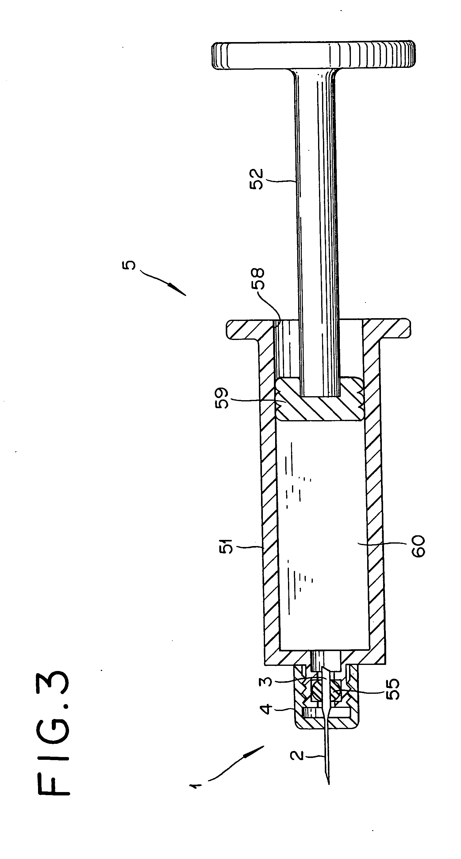
[0057]FIG. 3 is a cross sectional view of a drug injection apparatus equipped with a drug injection needle according to the invention; FIG. 4 is a cross sectional view of a drug injector main body show in FIG. 3; FIG. 5 is a side view of the drug injection needle show in FIG. 3; and FIG. 6 is a cross sectional view of the drug injection needle show in FIG. 3.

[0058] The drug injection apparatus shown in FIG. 3 includes a drug injection needle 1 and an injector main body 5, and injects liquid drug 60 through the distal end of the drug injection needle 1 when a plunger 52 is pushed.

[0059] As shown in FIG. 4, the injector main body 5 comprises a drug container 51, which is of a substantially cylindrical shape and holds the liquid drug 60 inside, and the plunger 52 that is capable of moving reciprocally and axially inside the drug container 51.

[0060] A drug injection port 54 is formed on a boss 53 provided on the distal end (left hand side in the drawing) of the drug container 51, this...

second embodiment

[0097] The outer diameter of the drug introducing needle part 3a in the second embodiment should be preferably in the range of 0.3-2 mm, or more preferably in the range of 0.35-1.5 mm. Accordingly, the inner diameter of the drug introducing needle art 3a should be preferably in the range of 0.25-1.2 mm.

[0098] The affixing of the puncturing needle part 2a and the rug introducing needle part 3a to the housing 4a is conducted by insert molding or gluing, for example, in a shape as shown in FIG. 11. Since the puncturing needle part 2a and the drug introducing part 3a are formed of two separate needle bodies as shown in FIG. 11, the drug injection needle la can be manufactured by a conventional method without requiring any special method. Moreover, since the needle parts 2a and 3a are assembled to engage with the attaching holes 44a and 45a respectively, they are firmly affixed to the housing 4a.

[0099] If the drug injection needle la is a long needle normally used for subcutaneous and i...

third embodiment

[0111] The outer diameter of the drug introducing needle part 3b in the third embodiment should be preferably in the range of 0.3-2 mm, or more preferably in the range of 0.35-1.5 mm. Accordingly, the inner diameter of the drug introducing needle part 3b should be preferably in the range of 0.25-1.2 mm.

[0112] The affixing of the puncturing needle part 2b to the housing 4b is conducted by insert molding or gluing, for example, in a shape as shown in FIG. 16. Since the drug introducing part 3b is formed integrally with the housing 4b from the same material as shown in FIG. 16, the drug injection needle 1b can be manufactured by a conventional method without requiring any special method. Moreover, since the puncturing needle part 2b is assembled to engage with the attaching hole 44b, it is firmly affixed to the housing 4b.

[0113] If the drug injection needle 1b is a long needle normally used for subcutaneous and intramascular administration, it is not necessary to make the entire porti...


PUM


Abstract

A drug injection needle 1 comprises a puncturing needle part 2 that has a puncturing part 21 that is capable of puncturing a body, a drug introducing needle part 3 that is capable of communicating with the inside of the drug container, and a housing 4 that supports the puncturing needle part 2 and the drug introducing needle part 3 in such a way as to allow the liquid drug to flow between the needle parts 2 and 3. The outer diameter of the puncturing part 21 is not more than 0.254 mm. The outer diameter of the drug introducing needle part 3 is larger than at least that of the vicinity of the distal end of the puncturing part 21 of the puncturing needle part 2, and a cutting edge 31 is formed at the end of the drug introducing needle part 3 for penetrating through an elastic member that is provided to seal the drug injection port of the drug container.

Description

BACKGROUND OF THE INVENTION [0001] 1. Field of the Invention [0002] The invention relates to an injection needle and an injection apparatus, more specifically to an injection needle and an injection apparatus used for injecting liquid drugs into a body. [0003] 2. Description of the Related Art [0004]FIG. 1 and FIG. 2 show a typical injection needle used for injecting liquid drugs into a living body, particularly intradermal, subcutaneous, and muscle tissue layers. [0005] As shown in these drawings, a drug injection needle 101 consists of a needle 102 and a base 104 that supports the needle 102. The needle 102 consists of a hollow needle of a constant outer diameter and is affixed to the base 104. A cutting edge 131 is formed at the proximate end of the needle 102. Furthermore, a female screw 143 is formed on the internal surface of the base 104. [0006] The drug injection needle 101 is typically attached to the drug injection port formed on the nose of a drug container (not shown) co...

Claims


Application Information

Patent Timeline
Patent Type & Authority Applications(United States)
IPC IPC(8): A61M5/158A61M5/28A61M5/32A61M5/34
CPCA61M5/288A61M5/347A61M5/343A61M5/329
Inventor OOYAUCHI, TETSUYA
Owner TERUMO KK
Why Eureka
Try Eureka