
Detection and identification of biopolymers using fluorescence quenching

a technology of biopolymer and quenching, applied in the field of biopolymer, can solve the problems of difficult or impossible to obtain information on the individual monomers of the biopolymer, and it is difficult to expect this simple tunneling configuration to provide the specificity required for biopolymer sequencing

Inactive Publication Date: 2005-05-05
AGILENT TECH INC
View PDF14 Cites 95 Cited by
  • Summary
  • Abstract
  • Description
  • Claims
  • Application Information

AI Technical Summary

Problems solved by technology

One desire of scientists is that the individual monomers of the biopolymer strand might be identified via the characteristics of the blockage current, but this hope may be unrealized because of first-principle signal-to-noise limitations and because the naturally occurring nanopore is thick enough that several monomers of the biopolymer are present in the nanopore simultaneously.
However, as is the case with single-stranded biopolymers passing through naturally occurring nanopores, first-principle signal-to-noise considerations make it difficult or impossible to obtain information on the individual monomers in the biopolymer.
For this reason, it is difficult to expect this simple tunneling configuration to provide the specificity required to perform biopolymer sequencing.
Conceptually, it is also possible to inject a known current between the conductors and measure the resulting voltage, but this approach can fail if the characteristic current versus voltage has a negative slope region.
The problem with many of these techniques regards the ability to actually obtain measurements from the biopolymers that translocate through nanopores.
However, to date no concrete experimental data exists to show that this is actually possible.
The problem with many phosphorescence or fluorescence techniques is that they become rather difficult to control how and when a quencher molecule contacts a fluorophore or chromophore.
However, cited references or art are not admitted to be prior art to this application.

Method used


Image

  • Detection and identification of biopolymers using fluorescence quenching
  • Detection and identification of biopolymers using fluorescence quenching
  • Detection and identification of biopolymers using fluorescence quenching

Examples


Embodiment Construction

[0019] This invention is not limited to specific compositions, methods, steps, or equipment, as such may vary. The terminology used herein is for the purpose of describing particular embodiments only, and is not intended to be limiting. Methods recited herein may be carried out in any order of the recited events that is logically possible, as well as the recited order of events. Furthermore, where a range of values is provided, it is understood that every intervening value, between the first and second limit of that range and any other stated or intervening value in that stated range is encompassed within the invention. Also, it is contemplated that any optional feature of the inventive variations described may be set forth and claimed independently, or in combination with any one or more of the features described herein.

[0020] Unless defined otherwise below, all technical and scientific terms used herein have the same meaning as commonly understood by one of ordinary skill in the ...


PUM

PropertyMeasurementUnit
Diameteraaaaaaaaaa
Diameteraaaaaaaaaa
Structureaaaaaaaaaa

Abstract

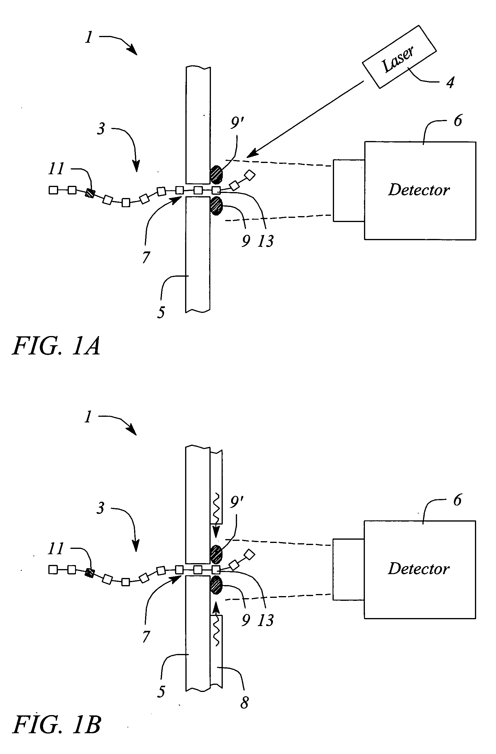
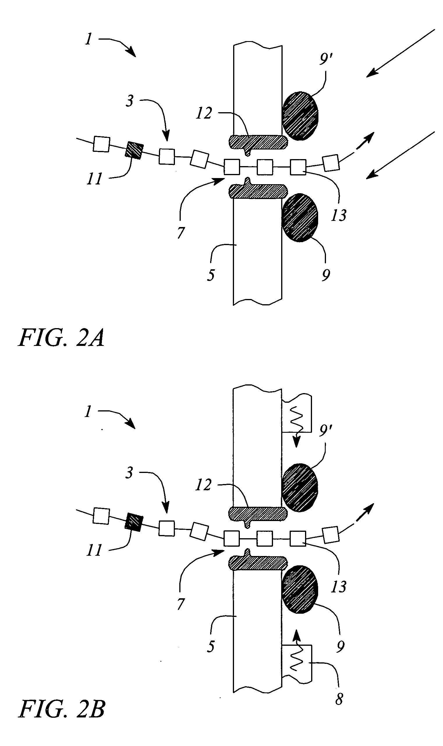
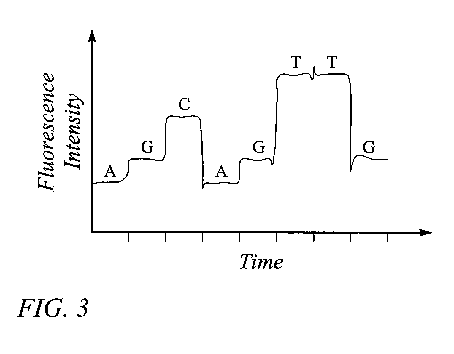
The present invention provides an apparatus for detecting a nanoscale moiety and a method for sensing a nanoscale moiety. The apparatus includes a substrate having a nanopore, at least one excitable molecule attached to the substrate adjacent to the nanopore, and a light source for exciting the excitable molecule attached to the substrate adjacent to the nanopore wherein the excitable molecule is quenched by the quencher molecule on the nanoscale moiety as it passes by the excitable molecule. The invention also includes a method for detecting the presence or identity of the nanoscale moiety.

Description

TECHNICAL FIELD [0001] The invention relates generally to the field of biopolymers and more particularly to an apparatus and method for identifying and characterizing biopolymer molecules. BACKGROUND [0002] Techniques for manipulating matter at the nanometer scale (“nanoscale”) are important for many electronic, chemical and biological purposes (See Li et al., “Ion beam sculpting at nanometer length scales”, Nature, 412: 166-169, 2001). Among such purposes are the desire to more quickly sequence biopolymers such as DNA. Nanopores, both naturally occurring and artificially fabricated, have recently attracted the interest of molecular biologists and biochemists for the purpose of DNA sequencing. [0003] It has been demonstrated that a voltage gradient can drive a biopolymer such as single-stranded DNA (ssDNA) in an aqueous ionic solution through a naturally occurring transsubstrate channel, or “nanopore,” such as an α-hemolysin pore in a lipid bilayer. (See Kasianowicz et al., “Charact...

Claims


Application Information

Patent Timeline
IPC IPC(8): B01L3/00G01N21/64G01N33/542G01N33/68
CPCB01L3/5027B82Y15/00G01N21/6428G01N2021/6432G01N33/542G01N33/6803G01N33/48721
Inventor PITTARO, RICHARD J.VERDONK, EDWARD D.DOHERTY, THOMAS P.
Owner AGILENT TECH INC
Learn More