
Laser welded tube fitting structure and gas generator with the tube structure

a gas generator and welding tube technology, applied in the direction of manufacturing tools, vehicular safety arrangements, pedestrian/occupant safety arrangements, etc., can solve the problems of limited steel used and cracks on the surface of weld metals

Inactive Publication Date: 2005-05-05
NIPPON KAYAKU CO LTD
View PDF9 Cites 15 Cited by
  • Summary
  • Abstract
  • Description
  • Claims
  • Application Information

AI Technical Summary

Benefits of technology

[0058] The laser welded joint structure as described above can provide advantageous effects that generation of a crack having bad influence on performance of the welded portion is completely prevented, that the welded portion is improved in quality, that the number of welding steps and inspection and repair steps is largely reduced, and that manufacture costs are largely reduced.
[0059] Next, the laser welded joint structure of the above-described embodiment will be described by means of specific Examples.

Problems solved by technology

However, an attempt to obtain a weld-penetration of a certain depth, e.g., 1.5 mm or more, at a welding speed of 0.5 m / min or higher has resulted in a problem that a surface of a weld metal suffers from a crack.
However, this approach involves a problem that kinds of steel used are limited.

Method used


Image

  • Laser welded tube fitting structure and gas generator with the tube structure
  • Laser welded tube fitting structure and gas generator with the tube structure
  • Laser welded tube fitting structure and gas generator with the tube structure

Examples


example 1

[0060] Referring to FIG. 4, a steel material of SPG according to Japanese Industrial Standard G3452 having a phi, ø, of 60.5 mm and a plate thickness of 3.5 mm was machined into a cylindrical shape to thereby form a first steel member 1. Further, a steel material of SPCD according to Japanese Industrial Standard G3141 having a plate thickness of 3 mm was press-molded and then machined, to thereby form a cylindrical second steel member 2 provided with a flange portion.

[0061] The first steel member 1 was fitted into the second steel member 2, and thus formed was a flare groove joint 7 having a flare single bevel groove.

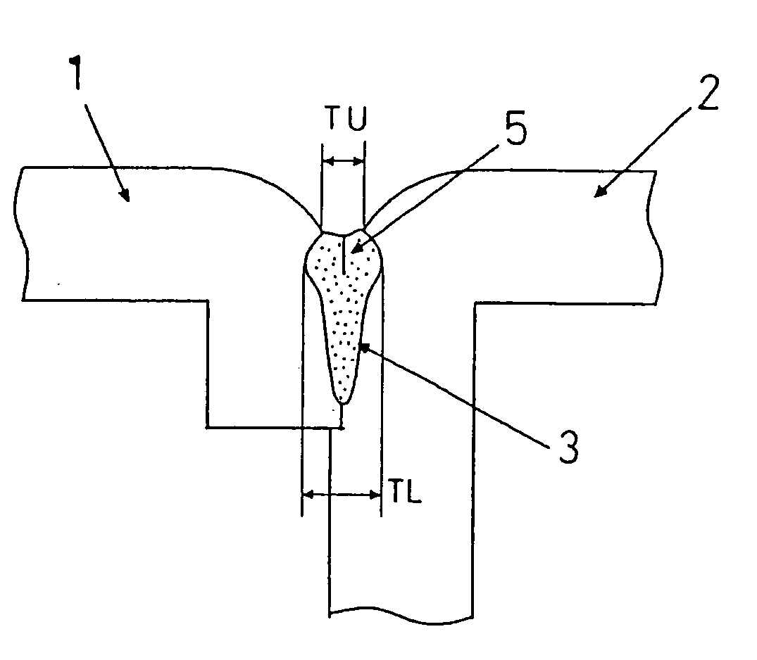
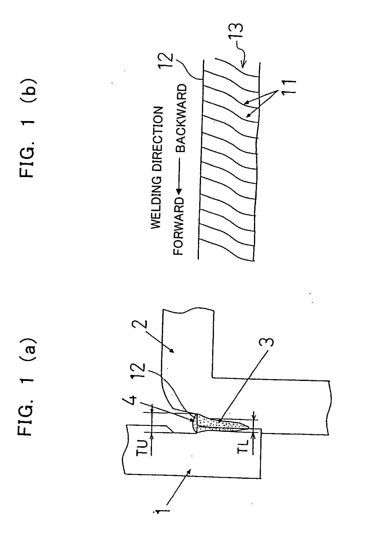
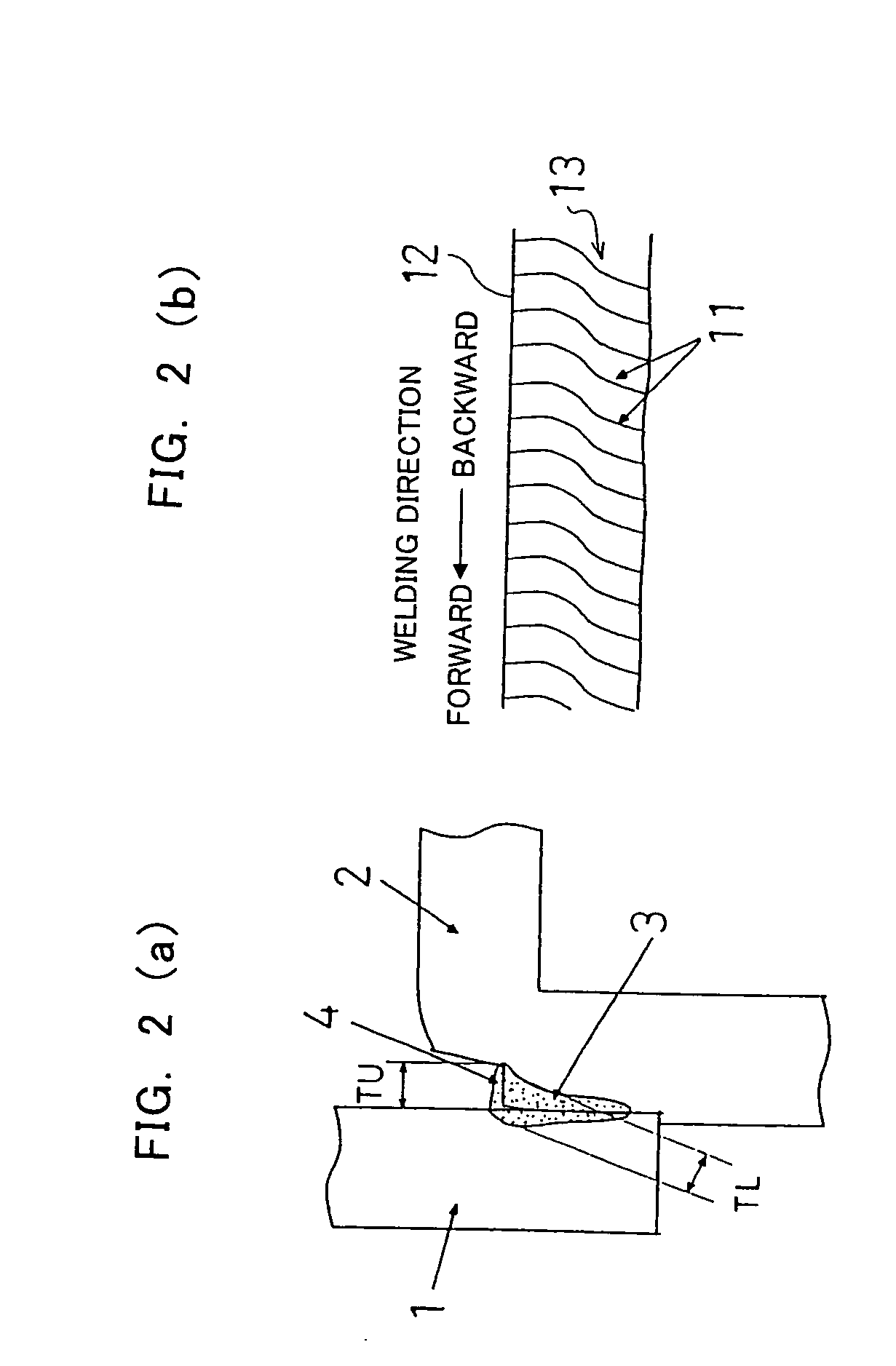
[0062] Then, as shown in FIG. 5(b), a flat portion 4 for forming a square-like groove was formed on the second steel member. A width of the flat portion 4 was set at TS [mm].

[0063] Alternatively, as shown in FIG. 5(c), a flat portion 4 for forming a square-like groove was formed on both the first and second steel members. A width of the flat portion 4 was set at TD [...

example 2

[0072] Referring to FIG. 7, a steel material of SPCD according to Japanese Industrial Standard G3141 having a plate thickness of 3 mm was press-molded and then machined, to thereby form a disc-shaped first steel member 1. The first steel member 1 was assembled to and fitted into a second steel member 2 having a flange portion, and thus formed was a flare groove joint 7 having a flare single V groove.

[0073] Then, as shown in FIG. 8(c), a flat portion 4 for forming a square-like groove was formed on both the first and second steel members. A width of the flat portion 4 was set at TD [mm].

[0074] A YAG laser-welding was performed thereon, and then a surface and a section of a welded portion were examined for presence or absence of generation of a crack.


PUM

PropertyMeasurementUnit
widthaaaaaaaaaa
depthaaaaaaaaaa
widthaaaaaaaaaa

Abstract

There is provided a laser welded joint structure for a flare groove joint, wherein a flat portion 4 for forming a square-like groove in the flare groove is formed at a beam-injected portion of the flare groove on at least one side of welded members 1 and 2. There is also provided a gas generator comprising the above-described laser welded joint structure.

Description

TECHNICAL FIELD [0001] The present invention relates to a welded joint structure in which two welded members, such as a press-molded steel member and a press-molded steel member or such as a press-molded product and a steel member, are jointed to each other by means of laser welding. [0002] Particularly, the present invention relates to a laser welded joint structure for a flare groove joint in which a groove is, in a sectional view, made up of two arcs or made up of an arc and a straight line. [0003] Examples of the welded members include steel materials, etc., that constitute car components such as gas generators, building components, household appliance components, and the like. [0004] A groove that is, when seen in a section of a flare groove joint, made up of two arcs is hereinafter referred to as “flare single V groove”. A groove that is, when seen in a section of a flare groove joint, made up of an arc and a straight line is hereinafter referred to as “flare single bevel groo...

Claims


Application Information

Patent Timeline
Patent Type & Authority Applications(United States)
IPC IPC(8): B23K26/28B23K33/00B60R21/26B60R21/263B60R21/264
CPCB23K26/28B23K26/285B23K33/006B23K2201/06Y10T403/479B60R2021/26076B60R2021/2633B60R2021/2648B60R21/2644B23K26/282B23K2101/06
Inventor MURAI, YASUOAOKI, YASUHIRO
Owner NIPPON KAYAKU CO LTD
Learn More