
Media drive cage having improved insertion shock and air flow properties

a media drive and cage technology, applied in the direction of electric apparatus casings/cabinets/drawers, instruments, record information storage, etc., can solve the problems of media drive damage, drive damage, and disk drive shock, and achieve the effect of facilitating better cooling for the devi

Active Publication Date: 2005-05-05
HEWLETT PACKARD DEV CO LP
View PDF6 Cites 16 Cited by
  • Summary
  • Abstract
  • Description
  • Claims
  • Application Information

AI Technical Summary

Benefits of technology

[0004] A media drive cage according to a preferred embodiment of the invention has improved insertion shock and air flow properties.
[0005] In one aspect, a first slot in the cage may be configured to receive a first protrusion of a media drive housing. The slot defines a plane of movement as the protrusion travels through it. A first spring disposed adjacent to the slot engages the protrusion as it travels; but, in response to force exerted by the protrusion, the spring deflects outward in a direction orthogonal to the plane of movement. The spring engages the protrusion just before it reaches the end of the slot, causing the media drive to slow down prior to reaching a fully engaged position within the cage. This frictional slowing reduces mechanical shock to the drive when its movement stops.
[0006] In another aspect, a resilient finger disposed at the end of the first or a second slot engages a protrusion of the drive when the drive reaches its fully inserted position, thus further reducing mechanical shock.
[0007] In another aspect, a second spring may engage a protrusion of the drive as the drive enters one of the slots. The second spring causes additional slowing of the drive during insertion. In addition, the second spring engages a protrusion of the drive when the drive has reached its fully engaged position in the cage. The engagement of the second spring with the protrusion helps to stabilize the drive in its inserted position, and dampens vibrations that may occur after the drive has reached its inserted position.
[0009] In yet another aspect, the slots may be nonlinear, including a high section between two low sections such that the high section clears the profile of the drive housing after it reaches its inserted position. The high section allows air to flow through the sides of the cage and over the drive, thus facilitating better cooling for the device.

Problems solved by technology

Many such drives—particularly hard disk drives—are sensitive to forces caused by mechanical shocks.
Consequently, the drives may be damaged or destroyed if they are not handled carefully.
One common scenario in which media drives are frequently damaged is during installation of the drives into a computer chassis.
But the high insertion force causes a high mechanical shock when the drive suddenly stops moving after reaching its engaged position in the cage or frame.
Such high mechanical shocks can damage the drive, resulting in a failure of the computer when power is initially applied.

Method used


Image

  • Media drive cage having improved insertion shock and air flow properties
  • Media drive cage having improved insertion shock and air flow properties
  • Media drive cage having improved insertion shock and air flow properties

Examples


Embodiment Construction

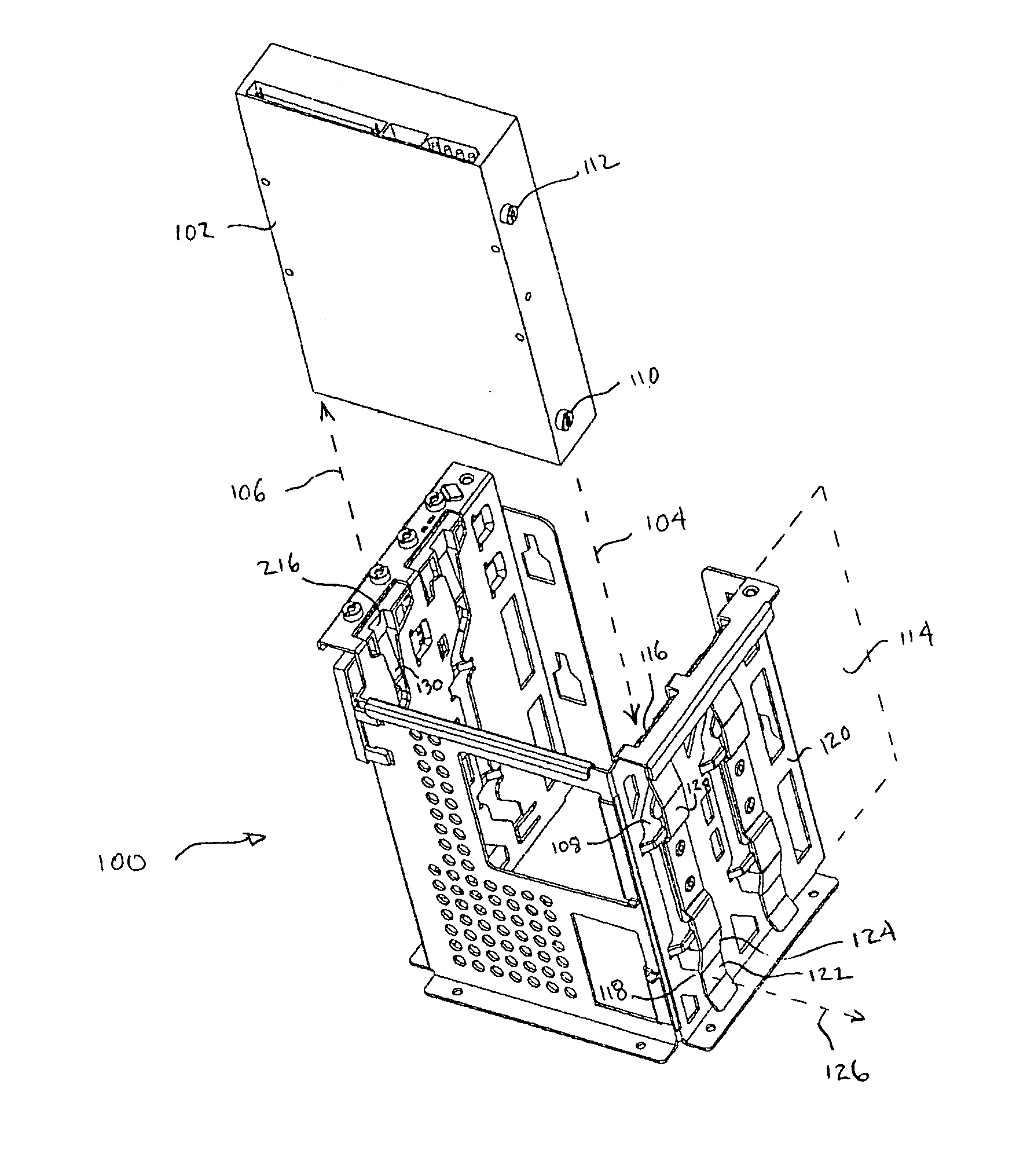
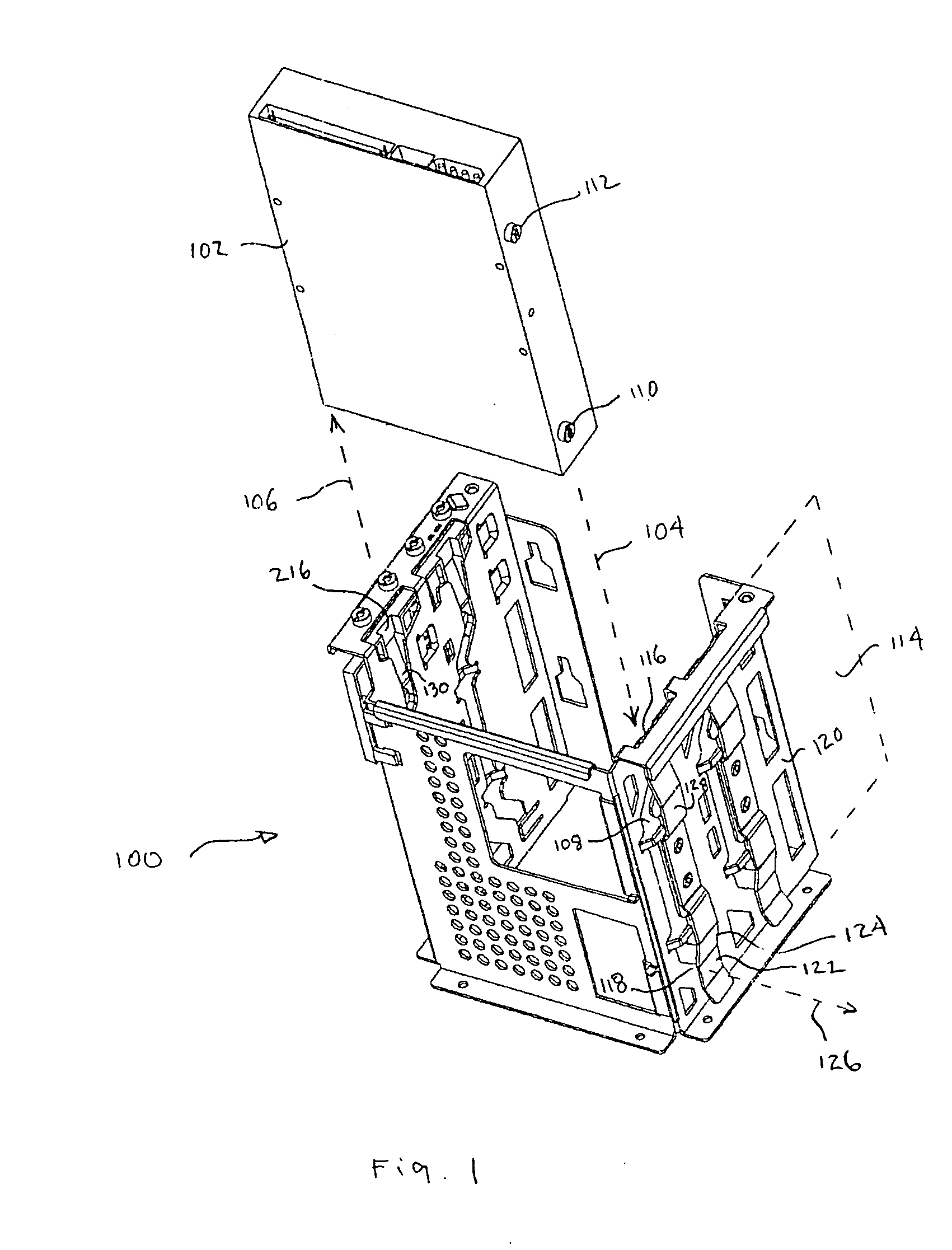
[0019]FIG. 1 illustrates a media drive cage 100 according to a preferred embodiment of the invention. A media drive 102, such as a disk drive, optical drive, tape drive or the like, is shown poised above cage 100. Drive 102 may be inserted into cage 100 in direction of insertion 104, or removed from cage 100 in direction of removal 106. Cage 100 may be constructed using any suitable material such as sheet metal. In the embodiment shown, cage 100 houses two identical drive bays. In alternative embodiments, cage 100 may house a single drive bay or more than two drive bays.

[0020] A slot 108 is formed in cage 100 and is configured to receive protrusions 110, 112 extending from drive 102. In the embodiment shown, protrusions 110, 112 are the heads of mounting screws fastened to drive 102. In alternative embodiments, other similar protrusions may be used.

[0021] Slot 108 defines a plane of movement 114 for protrusions 110, 112 as they move along a path through the slot from an opening 11...


PUM


Abstract

A slot in a media drive cage receives a protrusion of a media drive housing. A spring adjacent to the slot engages the protrusion just before it reaches the end of the slot, causing the media drive to slow down prior to reaching a fully engaged position within the cage. The frictional slowing reduces mechanical shock to the drive when its movement stops. A resilient finger at the end of the slot further reduces shock. A resilient latch retains the drive within the slot. To remove the drive, the latch may be disengaged by pulling on a hook portion of the latch. The slot may be nonlinear to enable airflow through the slot and over the drive, thus facilitating cooling of the drive.

Description

FIELD OF THE INVENTION [0001] This invention relates generally to techniques for inserting and mounting media drives in a computer chassis. BACKGROUND [0002] Media drives for computers include a wide variety of devices such as disk drives, optical drives and tape drives. Many such drives—particularly hard disk drives—are sensitive to forces caused by mechanical shocks. Consequently, the drives may be damaged or destroyed if they are not handled carefully. [0003] One common scenario in which media drives are frequently damaged is during installation of the drives into a computer chassis. During manufacture, each drive is usually slid into a cage or frame of some kind, which cage or frame is fixed to the inside of the computer chassis. Because incentives exist for fast production, the drives are sometimes inserted into the cage or frame with high force in order to install them quickly. But the high insertion force causes a high mechanical shock when the drive suddenly stops moving aft...

Claims


Application Information

Patent Timeline
IPC IPC(8): G06F1/16G06F1/18G06F1/20G11B33/12G11B33/14
CPCG06F1/184G06F1/187G11B33/142G11B33/128G06F1/20
Inventor FRANKE, GREGFRAME, KENNETHRENFRO, GREG
Owner HEWLETT PACKARD DEV CO LP
Learn More