
Automated cosmetics dispenser for point of sale cosmetics products

Inactive Publication Date: 2005-05-05
FLUID MANAGEMENT LLC
View PDF19 Cites 93 Cited by
  • Summary
  • Abstract
  • Description
  • Claims
  • Application Information

AI Technical Summary

Benefits of technology

[0030] In another refinement, to prevent suspensions containing colorants or tints from engaging a neck portion of the container, the method also comprises inserting a bushing down into the neck of the container to prevent suspensions dispensed into the container from splashing upward or otherwise engaging the neck of the container during the adding of said suspensions.

Problems solved by technology

Not all cosmetic products are universally applicable.
Even more complicated are color cosmetics.
Stores find it a significant problem to stock all possible variations of a particular color cosmetic.
Certain problems are associated with the above-cited prior art in terms of the dispense functions.
Thus, the stationary manifold and nozzle design is impractical.
Another problems associated with current cosmetics dispensing machines relates to the viscosity of the ingredients.
Considering the small quantities that may be used for a cosmetics preparation at a point of sale, a large drip that is not transmitted to the container or an excess drip that is transmitted to the container may affect the color or quality of the resulting product.
Currently available dispensing systems do not accommodate or compensate for this drip problem.
Another problem associated with current dispensing systems for cosmetics relates to mixability.
When the ingredients that include one or more colorants are dispensed into a narrow neck container, the colorant may often splash or coat the neck of the container and, once the colorant material is disposed on that neck, it is very difficult to get that portion of colorant mixed into the final preparation.
Even high speed gyroscopic mixers will not distribute colorant disposed on the neck of a small bottle into the rest of the formulation after long periods of mixing.

Method used


Image

  • Automated cosmetics dispenser for point of sale cosmetics products
  • Automated cosmetics dispenser for point of sale cosmetics products
  • Automated cosmetics dispenser for point of sale cosmetics products

Examples


Embodiment Construction

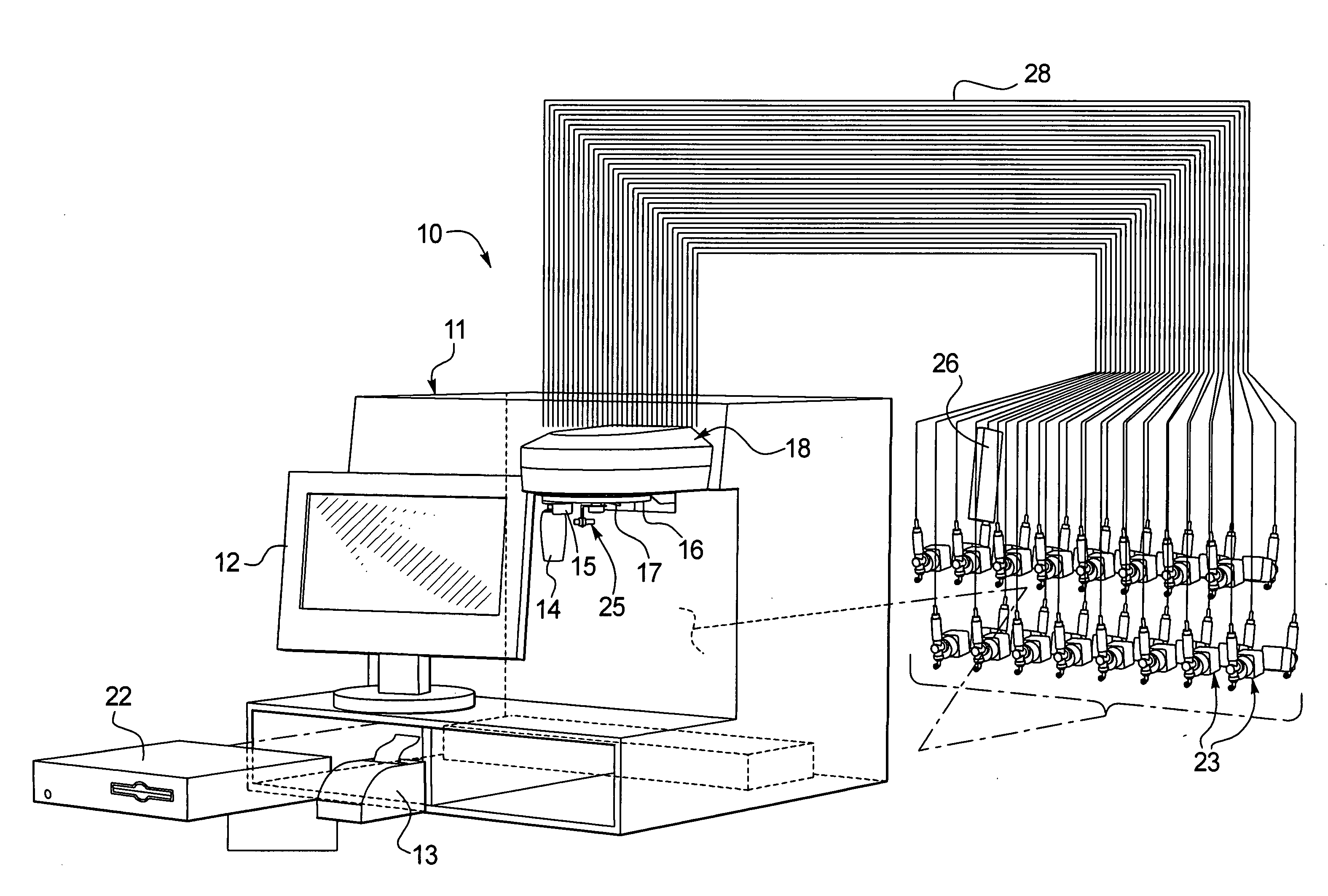
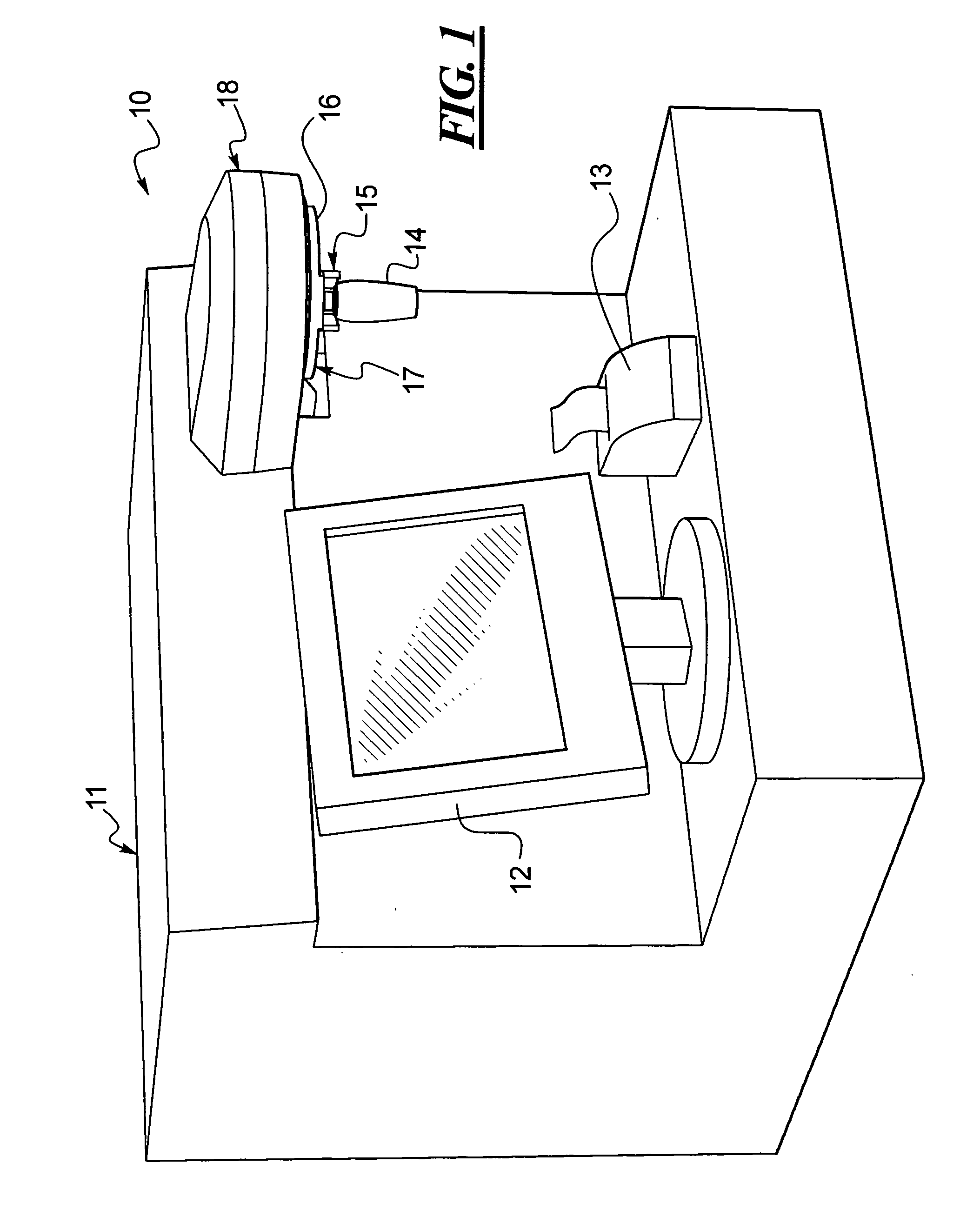
[0049] Turning to FIG. 1, an improved dispensing system 10 is disclosed. The dispensing system 10 includes a cabinet 11 enclosing the internal working parts which will be described below and which supports a touch screen 12 for inputting customer information and formula selection. The dispensing system 10 also includes a printer 13 for printing labels to be attached to the container 14 after the cosmetic preparation is dispensed therein. The container 14, during dispensing, is mounted to a container holder 15 disposed on an underside 16 of a turntable 17. The turntable 17 is disposed beneath an enclosing hood 18 which, as shown below in FIG. 3, provides an enclosure for the nozzle manifold 19.

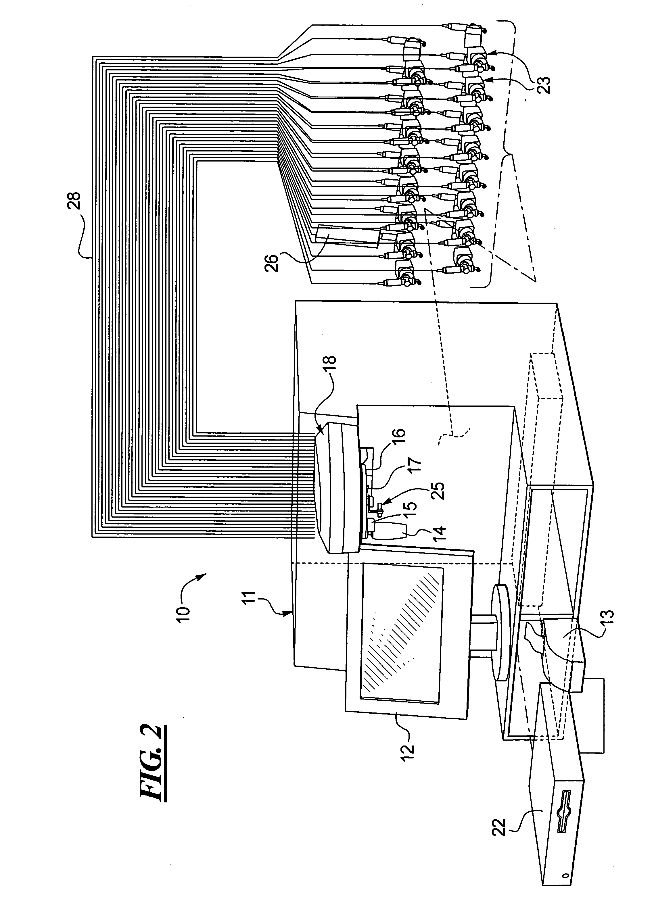
[0050] Turning to FIG. 2, the cabinet 11 also houses a controller or CPU 22 which is linked to the touch screen 12, the printer 13, the plurality of nutating pumps shown at 23, the motor 24 (see FIG. 3) that rotates the turntable 17 and the position sensor shown at 25.

[0051] Still referring t...


PUM

PropertyMeasurementUnit
Sizeaaaaaaaaaa
Flexibilityaaaaaaaaaa
Currentaaaaaaaaaa

Abstract

An improved cosmetics dispensing system that includes a controller, a plurality of mutating pumps, a plurality of reservoirs of cosmetics ingredients, a plurality of nozzles, a manifold for concentrically supporting the nozzles, a turntable rotatably connected beneath the manifold wherein the turntable includes a through opening for permitting the passage of fluid from one of the nozzles through the turntable, a motor for rotating the turntable, and wherein the controller is linked to each of the mutating pumps and the motor and each pump is in fluid communication with one of the reservoirs and vice versa and each pump is connected to one of the nozzles and vice versa. The system is computer operated whereby the turntable can rotate in either of the clockwise or counterclockwise directions and the turntable is equipped with a container holder that can accommodate containers of varying sizes. An improved method of dispensing ingredients for a cosmetic application at a point of sale is also disclosed which avoids coating an interior wall of the container with tints or colorants which are difficult to mix into the final solution once they engage the container wall or next surface.

Description

BACKGROUND [0001] 1. Technical Field [0002] An improved fully automated dispensing system for preparing cosmetics products at a point of sale is shown and described. The disclosed dispensing system utilizes nutating pump technology. An improved method of preparing a cosmetics product at a point of sale is also disclosed. [0003] 2. Description of the Related Art [0004] Multiple pump dispensing systems have been used in the paint industry. Specifically, such a dispensing system incorporating multiple pumps dispensing viscous fluids, such as paint colorant, from flexible packages is disclosed in U.S. Pat. No. 6,273,298, owned by the assignee of the present application. Typically, such systems include piston pumps mounted on a rotary turntable with each pump coupled to the flexible package containing a viscous fluid, such as a colorant. The turntable, with the pumps and packages mounted thereon, is rotated until the desired pump and package is disposed over the container to be filled. A...

Claims


Application Information

Patent Timeline
IPC IPC(8): A45D44/00B01F13/10B01F15/00B01F15/02B65B43/60B67D7/02
CPCA45D44/00B01F13/1055B01F13/1066G07F17/18B01F15/0201B01F15/0243B01F2215/0031B01F15/00123B01F33/846B01F33/84B01F35/20B01F35/7176B01F2101/21B01F35/712B01F35/7179
Inventor MILLER, WILLIAM A.FORD, SAMKHOO, CHRISTOPHERCLEVELAND, JAMES R.MUMFORD, JEFFREYRUMMELHART, DONALD A.OBRECHT, ANTONHANAWALT, RYANLEIDER, MARTYAMSLER, THOMAS J.
Owner FLUID MANAGEMENT LLC
Learn More