
Cable-stay cradle system

a cable stayed and cradle technology, applied in the field of bridges, can solve the problems of premature deterioration of pylons, deterioration of the structural integrity of individual cable strands, and expensive and time-consuming anchor installation

Inactive Publication Date: 2005-04-28
FIGG BRIDGE ENGINEERS
View PDF29 Cites 0 Cited by
  • Summary
  • Abstract
  • Description
  • Claims
  • Application Information

AI Technical Summary

Benefits of technology

The cable-stay cradle system enables cost-effective and efficient construction and inspection of cable stays, maintaining structural integrity by distributing compressive forces uniformly and reducing frictional wear, allowing for thinner pylons and extended lifespan of both the pylon and cable strands.

Problems solved by technology

Installation of anchors 17, 18 is also costly and time consuming since each anchor must be individually installed and inspected thereafter.
This frictional interaction over a period of time causes wear, and therefore deteriorates the structural integrity of the individual cable strands and hence cable stay 36.
Due to unpredictability of the manner in which the strands may bunch up, this vertical compressive force can be unevenly distributed and therefore result in premature deterioration of pylon 33.
Moreover, this vertical compressive force also results in premature deterioration of the individual strands themselves, and is of concern in addition to the deterioration resulting from frictional interaction between the individual strands, as discussed above.

Method used


Image

  • Cable-stay cradle system
  • Cable-stay cradle system
  • Cable-stay cradle system

Examples


Embodiment Construction

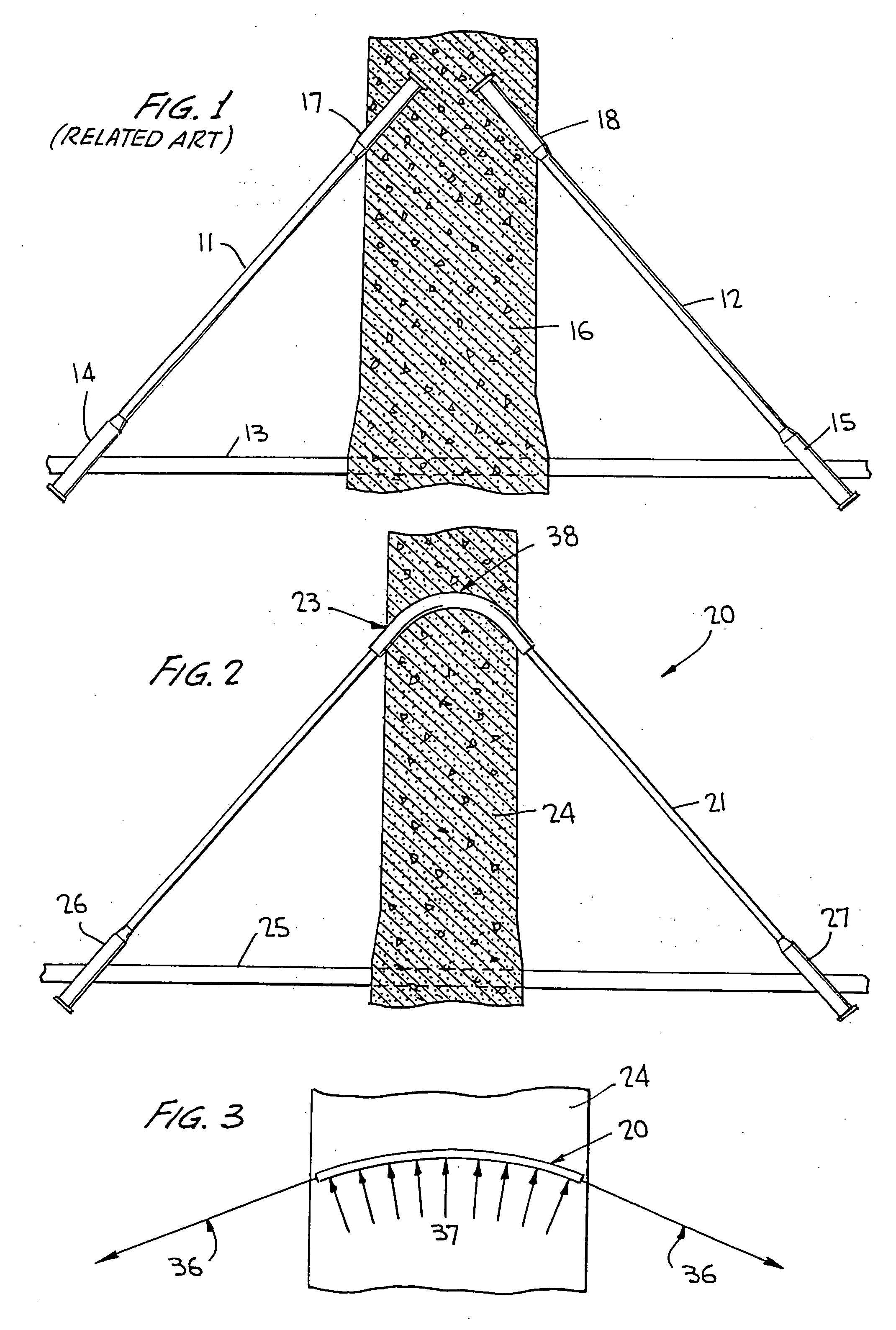
[0027] Referring now to the drawings wherein like reference numerals designate corresponding parts throughout the several views, FIG. 2 illustrates a cable-stay cradle system according to the present invention, generally designated 20.

[0028] Cable-stay cradle system 20 may be mounted onto vertically spaced cable stays 21 disposed at fixed or variable intervals in suitable pre-formed openings 23 along the vertical length of pylon 24. Cable stay 21 may be anchored to bridge deck 25 by suitable anchors 26, 27 in a conventional manner.

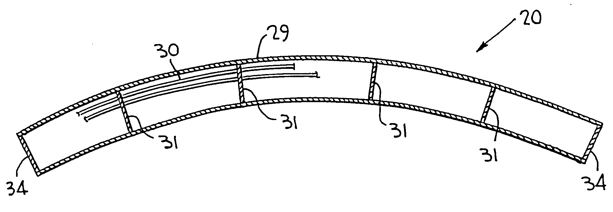
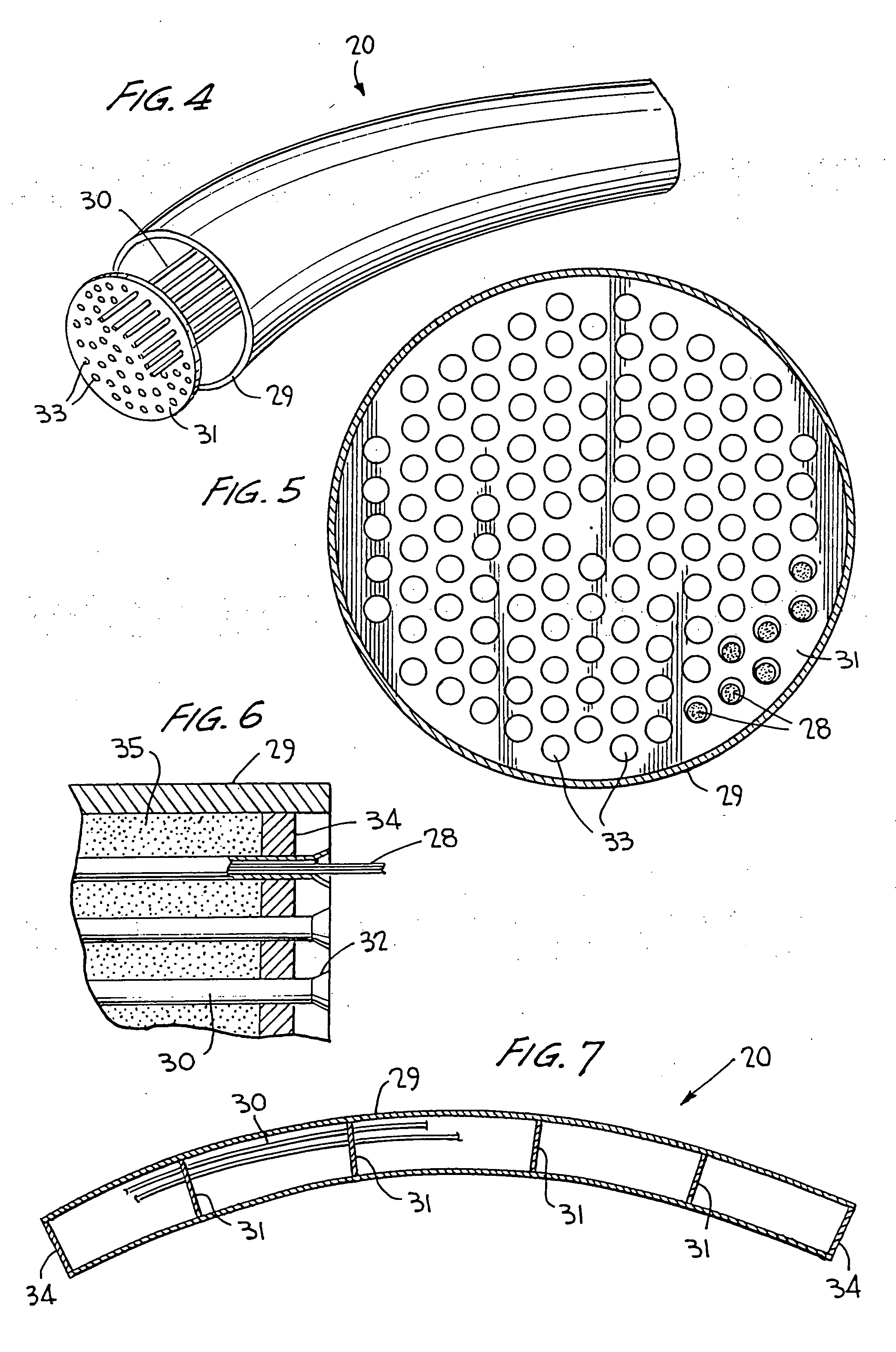
[0029] Referring to FIGS. 4-7, cable-stay cradle system 20 is shown in an assembled configuration having a plurality of cable strands 28 disposed therein, and includes a sheath 29. Cable strands 28 may extend along the length of cable stay 21. Each cable strand 28 may be individually disposed in a protective sleeve 30, and further maintained in spaced radial relationship by sleeve centering plate 31. Each protective sleeve 30 may include an enlarged end ...


PUM


Abstract

A cable-stay cradle system (“cradle system”) for cable stayed bridges is mounted onto a cable stay, the opposite ends of which are attached to anchors on a bridge deck. The cradle system is disposed along the length of the cable stay and located in a pre-formed opening in a pylon. The cradle system includes axially spaced sleeve centering plates that have radially spaced holes through which the cable strands of the cable stay are threaded. The cradle system ensures that a distance from center-points of adjacent cable strands remains essentially constant along the entire length of the cradle system. The invention also provides a method of installing a cable stay including a cradle system, which includes the steps of threading the cable stay through the opening in the pylon so as to locate the cradle system in the opening, and attaching the cable stay to anchors on the bridge deck.

Description

RELATED APPLICATIONS [0001] The present application claims the benefit of priority to Provisional Application Ser. No. 60 / 368,986, filed Apr. 2, 2002.BACKGROUND OF INVENTION [0002] a. Field of Invention [0003] The present invention relates generally to bridges, and more particularly, to cable stayed bridges in which cable stays are anchored to the bridge deck at one side of a pylon, extend through openings in the pylon, and are further anchored to the bridge deck at an opposite side of the pylon. [0004] b. Description of Related Art [0005] As shown in related art FIG. 1, in the past, cable stayed bridges have been constructed for example by anchoring cable stays 11, 12 to a bridge deck 13 by anchors 14, 15, respectively. Cable stays 11, 12 are further anchored to pylon 16 by anchors 17, 18, respectively. This conventional bridge construction technique has several drawbacks. For example, pylon 16 must be large enough to permit internal access during bridge construction for stressing ...

Claims


Application Information

Patent Timeline
Patent Type & Authority Applications(United States)
IPC IPC(8): E01D19/14
CPCE01D19/14
Inventor FIGG, EUGENE C. JR.FIGG, LINDAPATE, W. DENNEY
Owner FIGG BRIDGE ENGINEERS
Learn More