
Auxiliary handle, and hand power tool provided therewith

a technology of hand tools and auxiliary handles, which is applied in the direction of portable power-driven tools, manufacturing tools, drilling machines, etc., can solve the problems of inaccurate force application, low deformability of hand tools, and spongy and inaccurate feel of the hand during the utilization of the hand tools, so as to achieve accurate feedback, reduce deformability, and reduce the effect of deformation

Inactive Publication Date: 2005-04-21
ROBERT BOSCH GMBH
View PDF19 Cites 25 Cited by
  • Summary
  • Abstract
  • Description
  • Claims
  • Application Information

AI Technical Summary

Benefits of technology

[0005] Accordingly, it is an object of the present invention to provide an auxiliary handle as well as a hand tool, provided therewith which eliminate the disadvantages of the prior art.
[0006] In keeping with these objects and with others which will become apparent hereinafter, one feature of the present invention resides, briefly stated, in an auxiliary handle for a motor-driven hand tool, comprising a mounting device which forms an upper region and provides a force-transmitting and / or form-locking connection to a hand tool; a handle forming a lower region; a damping element forming an intermediate region and located at least locally between said mounting device and said handle, said damping element having a damping material with which, during an operation of a hand tool, it dampens vibrations transmitted through said mounting device to said handle, said damping element in its damping region acting for damping having at least one reinforcing region that has a lower deformability than a remaining part of said damping region and during deviations of said handle in at least two different directions relative to said mounting device causes differently great elastic counter forces.
[0007] When the auxiliary handle is designed in accordance with the present invention, it has the advantage that the damping element with a damping material damps vibrations which during the operation of the hand tool are transmitted via the mounting device to the handle, and simultaneously the force applied by the user in the working direction is transmitted substantially directly to the hand tool and the operator obtains an accurate feedback about the work in progress in the working direction. At least one reinforcing region acts so that a lower deformability is provided that the remaining damping region, during deviations of the handle in at least two different directions relative to the mounting direction with differently great, elastic counter forces.
[0012] It is advantageous when the at least one reinforcing region is composed of a material which is different from the damping material. The reinforcing region thereby is formed so that a material with a lower damping property, for example a reduced elasticity, is utilized when compared with the damping material.
[0014] It is advantageous when the at least one reinforcing region is formed as a connecting element between the mounting device and the handle. Thereby the transition between the mounting device and the handle is stabilized. In addition the connecting element can be manufactured especially simple, since recesses for the passages of the connecting are required.
[0018] It is advantageous when the at least one reinforcing region is formed so that the recess in at least one region of its ring-shaped extension is reduced. Thereby the recess has a smaller thickness and / or a smaller depth and Therefore also the damping element in this region is reduced, so that the elasticity of the damping element in this region is reduced and the reinforcing region is formed.

Problems solved by technology

With hand tools, in which during the operation the operator must apply a directional force, conventionally by pressing in direction of the working region, it is disadvantageous that the handle during the utilization of the tool has only a spongy and inaccurate feel for the operator during guidance of the hand tool.
Therefore the force application can be dosed only inaccurately, which leads to a not precise work with the hand tool.

Method used


Image

  • Auxiliary handle, and hand power tool provided therewith
  • Auxiliary handle, and hand power tool provided therewith
  • Auxiliary handle, and hand power tool provided therewith

Examples


Embodiment Construction

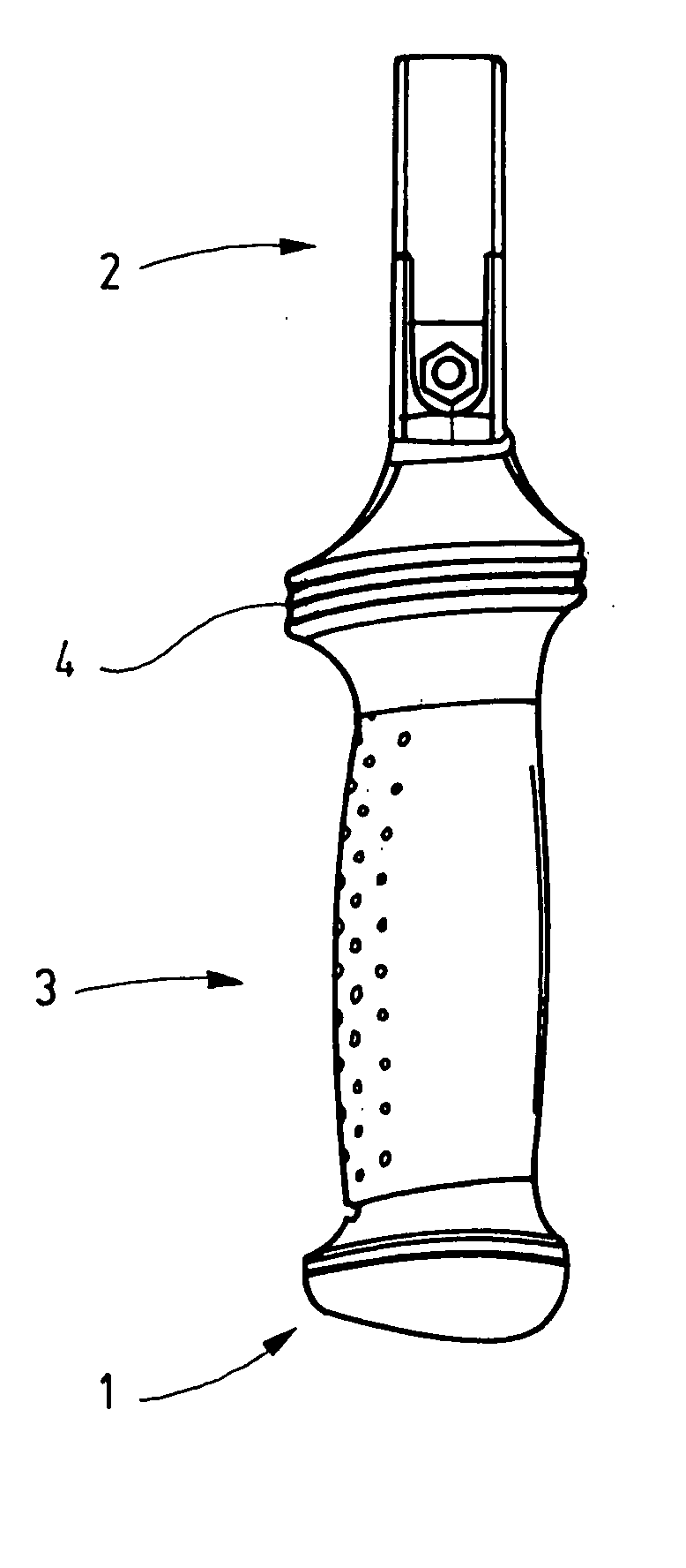
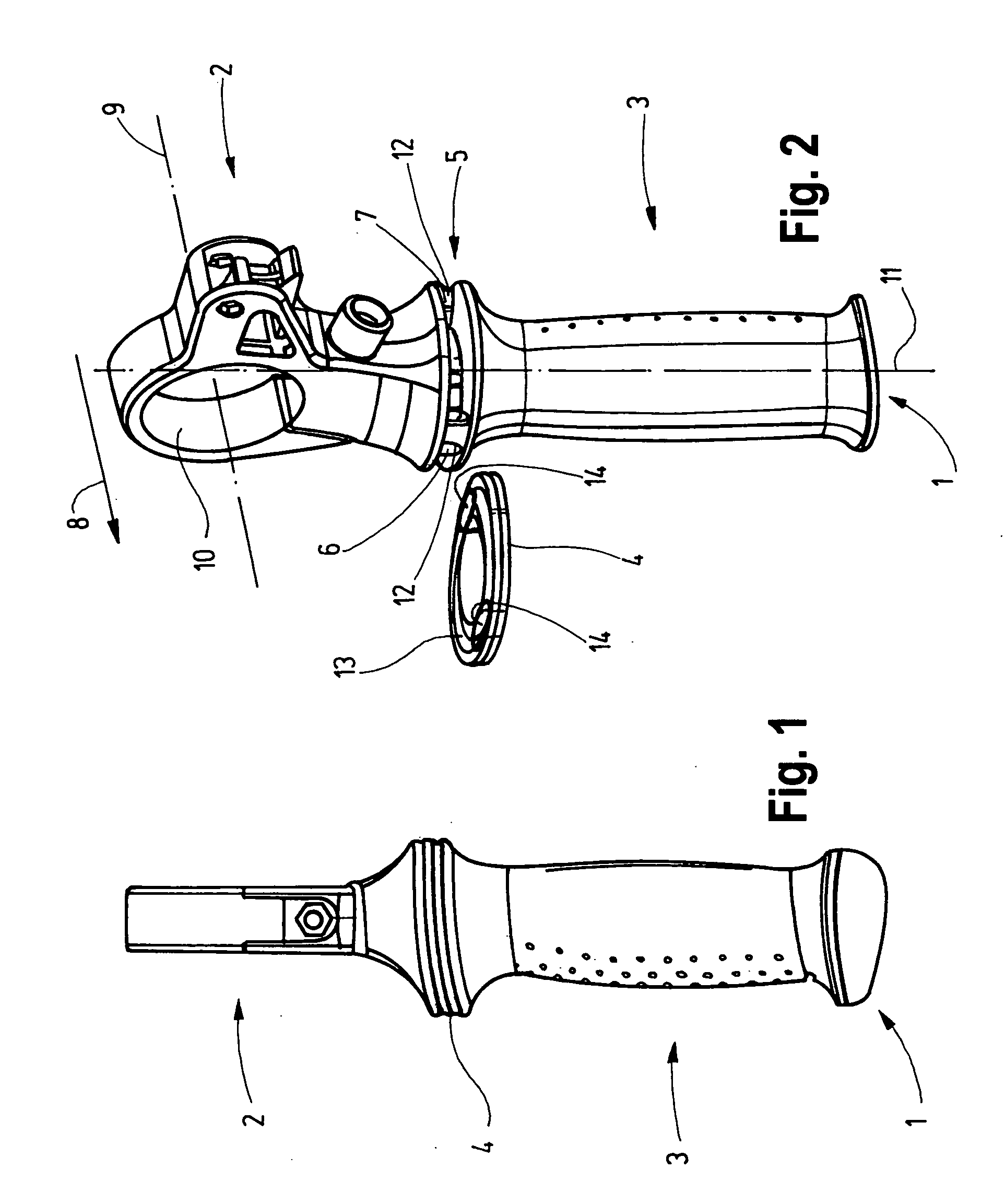
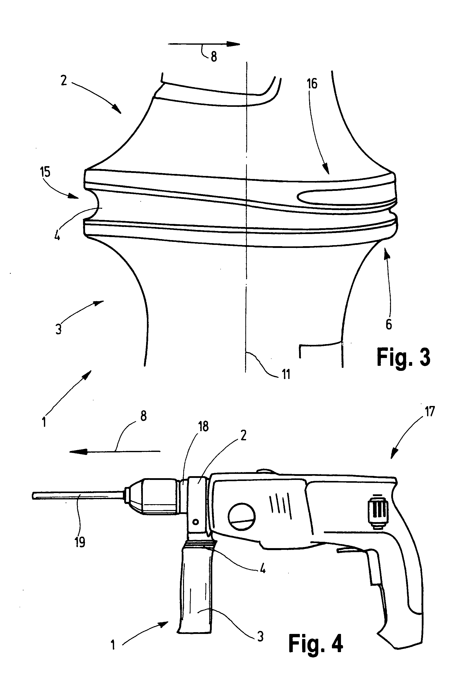
[0025]FIG. 1 shows an auxiliary handle 1 with a mounting device 2, a handle 3 and a damping element 4 arranged between the mounting device 2 and the handle 3.

[0026] Before the use of the auxiliary handle 1, the auxiliary handle 1 is fitted with its mounting device 2 over the clamping collar of a not shown hand tool and is mounted there in force-transmitting (non-positive) manner and / or form-locking (positive) manner. The vibration that are generated during the operation of the hand tool are transmitted through the clamping collar to the mounting device 2. Because of the damping element 4, these vibrations reach the handle 3 only in a dampened fashion.

[0027]FIG. 2 shows the auxiliary handle 1 in a front / slide view. The damping element 4, for clear visualization of the auxiliary handle, is removed. Two ribs-shaped reinforcing regions 6 and 7 are provided in an intermediate space 5 between the mounting device 2 and the handle. They are formed as parts of the handle 3. The working dir...


PUM

PropertyMeasurementUnit
forceaaaaaaaaaa
dampingaaaaaaaaaa
force consumptionaaaaaaaaaa

Abstract

An auxiliary handle for a motor-driven hand tool has a mounting device which forms an upper region and provides a force-transmitting and / or form-locking connection to a hand tool; a handle forming a lower region, a damping element forming an intermediate region and located at least locally between the mounting device and the handle, the damping element having a damping material with which, during an operation of a hand tool, it dampens vibration transmitted through the mounting device to the handle, the damping element in its damping region acting for damping having at least one reinforcing region that has a lower deformability than a remaining part of the damping region and during deviations of the handle in at least two different directions relative to the mounting device causes differently great elastic counter forces.

Description

BACKGROUND OF THE INVENTION [0001] The present invention relates to an auxiliary for a motor-driven hand tool, as well as to a motor-driven hand tool provided therewith. [0002] Auxiliary handles of the above mentioned type are known. They substantially include a mounting device and a handle. When the user of a motor-driven hand tool uses an auxiliary handle it can hold the hand tool during the operation with both hands and guide it correspondingly. If a hand tool during the work application needs an additional force consumption of the user in the working direction of the hand tool, in particular pressing of a power drill in direction of the longitudinal extension of the used drill, then with the auxiliary handle the user can apply the required force with two hands or arms. By means of the auxiliary handle, therefore greater hand tools or such tools which during the operation require a higher force consumption, can be operated more comfortably and more reliably. [0003] In hand tools ...

Claims


Application Information

Patent Timeline
Patent Type & Authority Applications(United States)
IPC IPC(8): B23B45/02B25D9/00B25F5/00B25F5/02B25G1/01
CPCB25F5/026B25F5/006
Inventor NICOLANTONIO, ALDO DISIMM, ROBERTHEINE, CHRISTIANISCH, SIMON
Owner ROBERT BOSCH GMBH
Learn More