Retractable screen system providing a positioning force for a movable sash

a technology of movable sashes and positioning devices, which is applied in the direction of door/window protective devices, window/door frames, door/window applications, etc., can solve the problems of requiring substantial physical effort, unable to meet the needs of solid core doors, and unable to meet the requirements of solid core doors

Inactive Publication Date: 2005-04-21
PELLA
View PDF99 Cites 5 Cited by
  • Summary
  • Abstract
  • Description
  • Claims
  • Application Information

AI Technical Summary

Benefits of technology

[0014] The present invention is also directed to a door with a window sash positioning device attached to the window sash that is releasably engagable with at least one contact surface on the vertical channel, such that the sash positioning device can engage the vertical channel at an infinite number of locations. The retractable screen assembly provides a continuous positioning force on the window sash.

Problems solved by technology

A basic problem with traditional hung windows designed to be raised and lowered by sliding within vertical jamb channels is how to retain the sash in a particular location.
Additionally, some positioning devices are not suitable for use on solid core doors since the pulley mechanisms are typically located in the hollow portion of the side frame members.
Some prior art devices have been known to either creep upward or downward from a selected position or else require substantial physical effort to overcome the frictional force of the positioning device.
Solutions to overcome these difficulties have been restricted because of the limitations relating to cost while maintaining simplicity of construction and the requisite reliability of operation.
In a related problem, consumers request various flexible screens that can be extended across the window opening.

Method used


Image

  • Retractable screen system providing a positioning force for a movable sash
  • Retractable screen system providing a positioning force for a movable sash
  • Retractable screen system providing a positioning force for a movable sash

Examples


Embodiment Construction

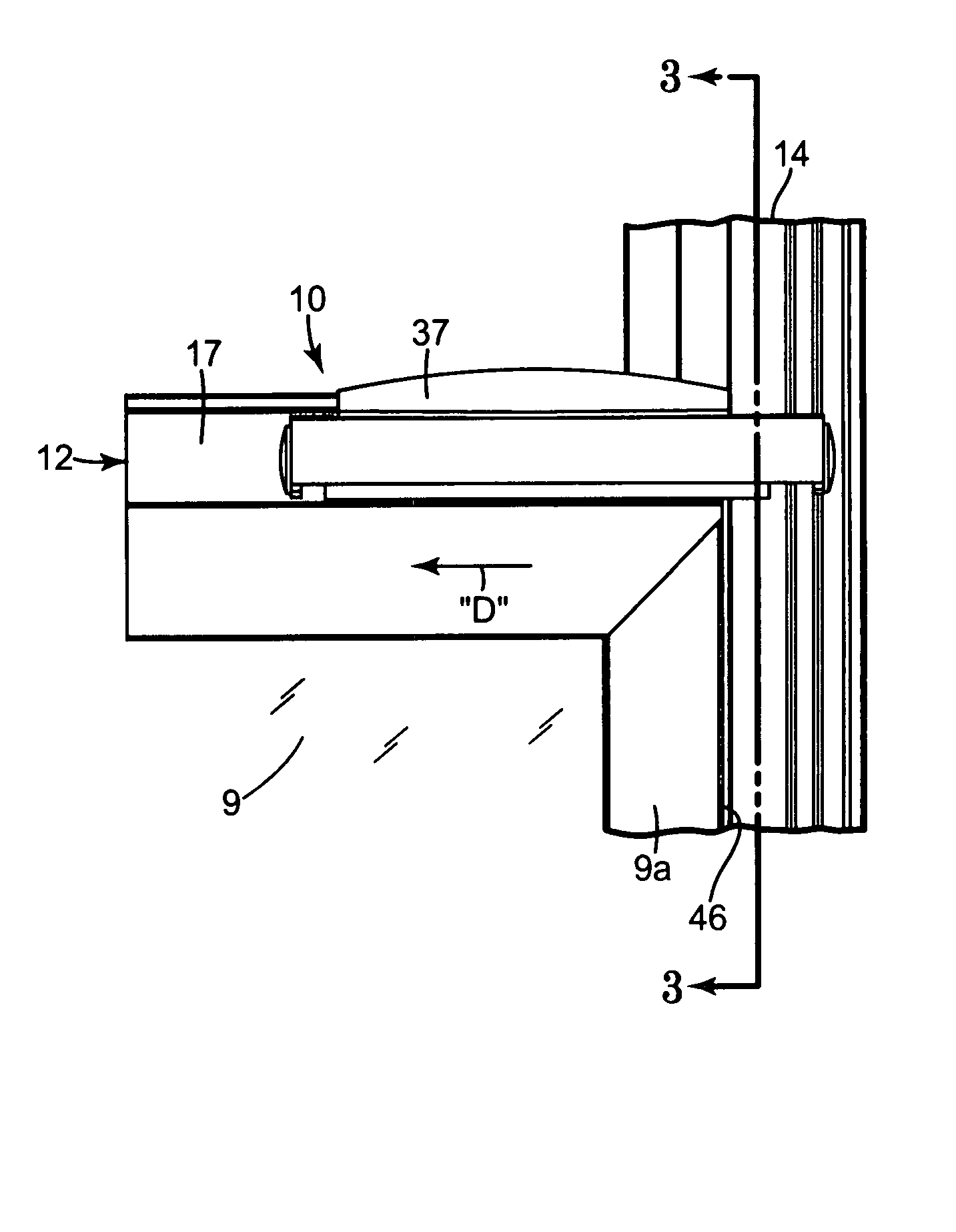
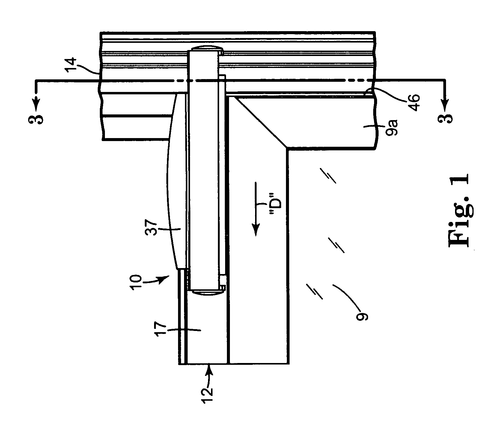
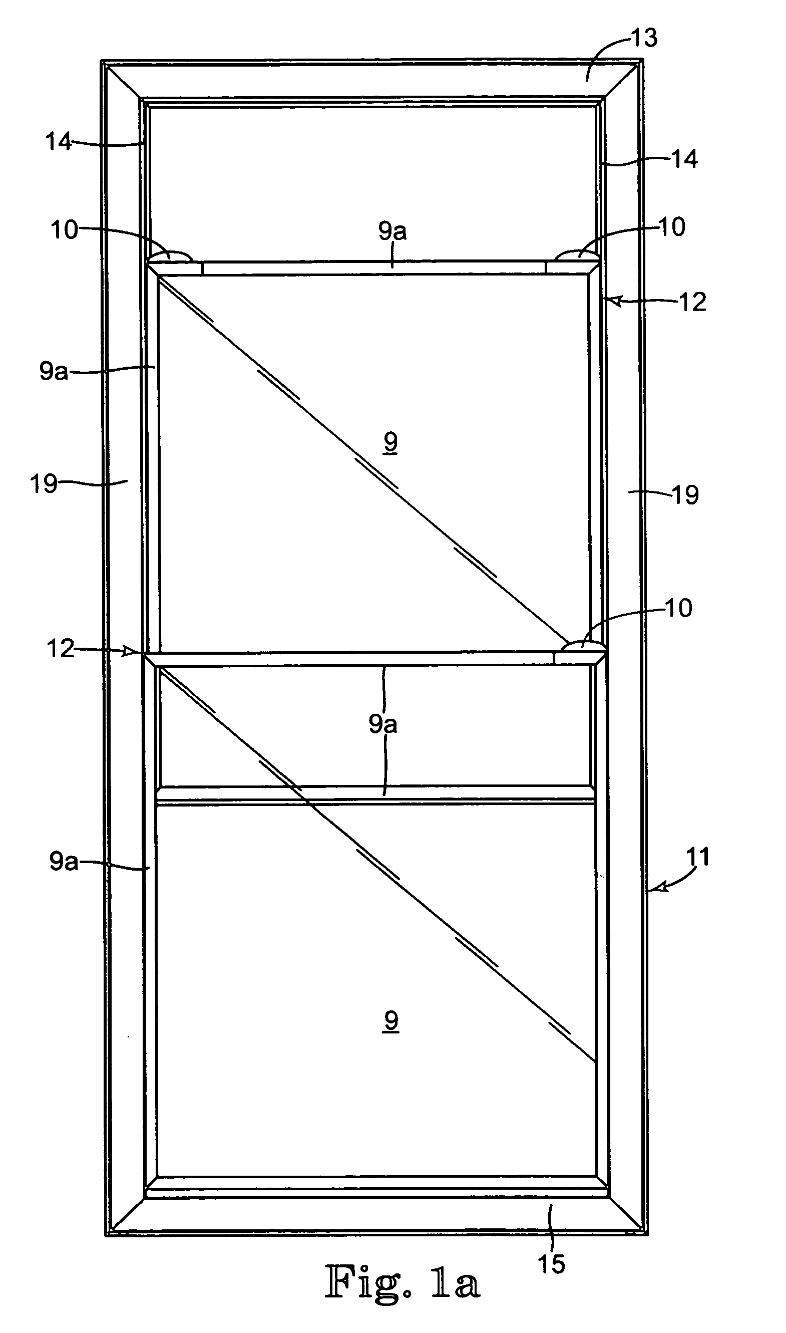
[0080]FIGS. 1, 1a and 2 illustrate various views of window pane 9 bordered by frame members 9a to form window sash 12 for fenestration product 11, such as a door or window. The window sash 12 is slidably mounted in a pair of vertical jamb channels 14 on frame members 19 of the fenestration product 11.

[0081] The spatial relationship of the vertical jamb channels 14 is maintained by a top rail 13 and a bottom rail 15. As best seen in FIG. 1a, the fenestration product 11 includes a pair of window sashes 12.

[0082] Each moveable window sash 12 is equipped with at least one sash positioning device 10. In the illustrated embodiment, the sash positioning device 10 is mounted to a wall 17 of window sash 12, although any of the surfaces can be used. Alternatively, in the embodiment of FIGS. 14a-14c, the sash positioning device is mounted on the doorjamb. As used herein, the“sash positioning device” refers to a mechanism that holds a movable window sash stationary within a vertical jamb chan...


PUM


Abstract

A door with a moveable window sash and a method of operating the same. The door includes vertical jambs with vertical channels. A window sash is movable in the vertical channels. A retractable screen assembly is attached to the door. The retractable screen assembly includes a roller, a flexible screen attached at a first end to the roller and at a second end to the movable window sash, and a biasing mechanism adapted to apply a continuous torque to the roller. The torque generates a positioning force on the window sash equal to at least 50% of the force of gravity acting on a window sash, such that the window sash can be positioned at an infinite number of locations along the vertical channels.

Description

FIELD OF THE INVENTION [0001] The present invention relates to a retractable screen system adapted to provide a positioning force for moveable sash in a fenestration product. The retractable screen extends and retracts across the opening created by movement of the sash. An infinite positioning device can optionally be used in combination with the retractable screen system. BACKGROUND OF THE INVENTION [0002] A basic problem with traditional hung windows designed to be raised and lowered by sliding within vertical jamb channels is how to retain the sash in a particular location. To overcome this problem, many different types of sash positioning devices have been developed to both retain the sash in a particular position and permit the sash to be moved easily when desired. For example, U.S. Pat. No. 3,080,620 discloses a storm window that uses spring loaded latches that engage with notches located at fixed intervals along the vertical window jamb. The storm windows can only be position...

Claims


Application Information

Patent Timeline
Patent Type & Authority Applications(United States)
IPC IPC(8): E06B5/00E06B9/40E06B9/90
CPCE06B5/003E06B9/90E06B9/40
Inventor ALLEN, RICHARDSTRATMOEN, TODD N.GONNERMAN, MICHAELBHARUCHA, RASHID DARAYUSGROMOTKA, GABRIELKIBBEL, KEITHCORY, STEVEN EDWARD
Owner PELLA
Why Eureka
Try Eureka