
Attachment device and methods of using the same

Active Publication Date: 2005-04-14
MEDTRONIC INC
View PDF63 Cites 888 Cited by
  • Summary
  • Abstract
  • Description
  • Claims
  • Application Information

AI Technical Summary

Benefits of technology

[0013] Yet another device for connecting a first mass to a second mass is disclosed. The device has a base, a first leg and a second leg. The base is curved. The base has a base diameter, a first end and a second end. The first leg has a first longitudinal axis and a first leg length. The first leg extends from the first end of the base. The second leg has a second longitudinal axis and a second leg length. The second leg extends

Problems solved by technology

This procedure is time consuming as doctors often use three to ten knots per suture.
During heart valve replacement procedures, the patient is on heart-lung bypass which reduces the patient's oxygen level and creates non-physiological bloodflow dynamics.
The longer a patient is on heat-lung bypass, the greater the risk for permanent health damage.
Existing suturing techniques extend the duration of bypass and increase the health risks due to heart-lung bypass.

Method used


Image

  • Attachment device and methods of using the same
  • Attachment device and methods of using the same
  • Attachment device and methods of using the same

Examples


Embodiment Construction

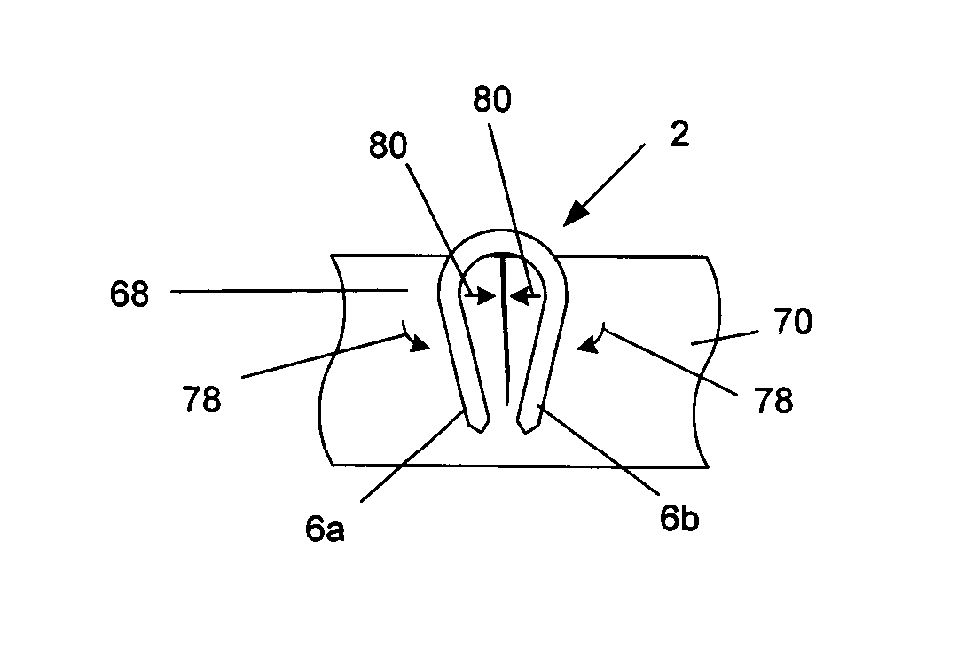
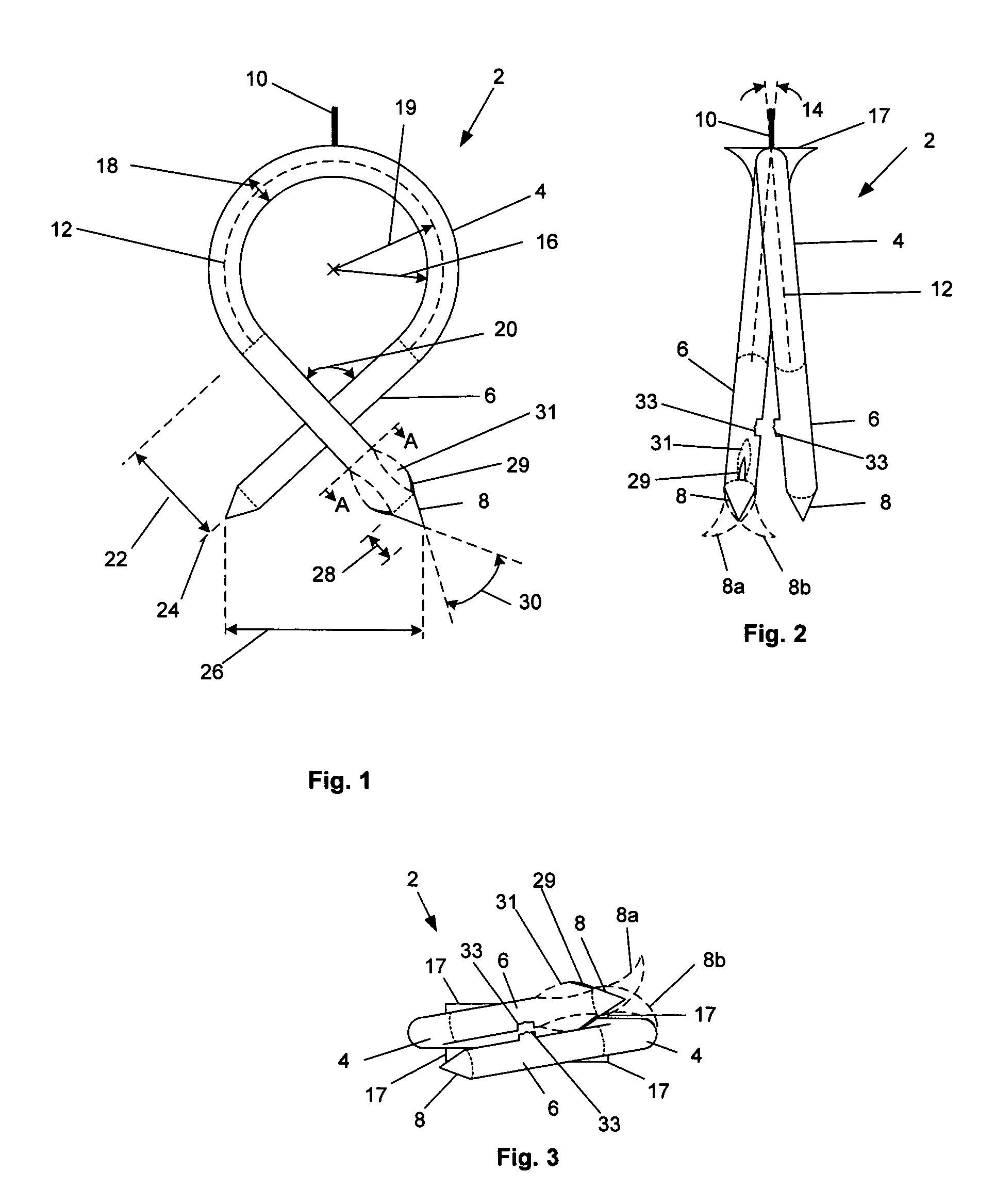
[0044]FIGS. 1 through 3 illustrate an attachment device 2. The attachment device 2 can have a base 4, legs 6, and a tip 8 at the end of each leg 6. (Phantom lines delineate the base 4, legs 6 and tips 8.) The base 4, legs 6 and tips 8 can be separate or integral elements. A flag 10 can be attached to, and extend from, the base 4. The base 4 and / or the legs 6 can be straight or curved.

[0045] The attachment device 2 can be made from a deformable or elastic material or a combination of materials having resulting deformable or elastic properties. The material can be, for example, stainless steel alloys, nickel titanium alloys (e.g., Nitinol), cobalt-chrome alloys (e.g., ELGILOY® from Elgin Specialty Metals, Elgin, Ill.; CONICHROME® from Carpenter Metals Corp., Wyomissing, Pa.), polymers such as polyester (e.g., DACRON® from E. I. Du Pont de Nemours and Company, Wilmington, Del.), polypropylene, polytetrafluoroethylene (PTFE), expanded PTFE (ePTFE), polyether ether ketone (PEEK), nylon,...


PUM


Abstract

Devices for attaching a first mass and a second mass and methods of making and using the same are disclosed. The devices can be made from an resilient, elastic or deformable materials. The devices can be used to attach a heart valve ring to a biological annulus. The devices can also be used for wound closure or a variety of other procedures such as anchoring a prosthesis to surrounding tissue or another prosthesis, tissue repair, such as in the closure of congenital defects such as septal heart defects, tissue or vessel anastomosis, fixation of tissue with or without a reinforcing mesh for hernia repair, orthopedic anchoring such as in bone fusing or tendon or muscle repair, ophthalmic indications, laparoscopic or endoscopic tissue repair or placement of prostheses, or use by robotic devices for procedures such as those above performed remotely.

Description

BACKGROUND OF THE INVENTION [0001] 1. Field of the Invention [0002] The present invention relates generally to a device for attaching a first mass to a second mass and methods of making and using the same. [0003] 2. Description of the Prior Art [0004] Prosthetic heart valves can replace defective human valves in patients. Prosthetic valves commonly include sewing rings, suture cuffs or rings that are attached to and extend around the outer circumference of the prosthetic valve orifice. [0005] In a typcal prosthetic valve implantation procedure, the aorta is incised and the defective valve is removed leaving the desired placemenr site that mayninclude a fibrous tissue layer or annular tissue. Known heart valve replacement techniques include individually passing sutures through the fibrous tissue or desired placements site within the valve annulus to form an array of sutures. Free ends of the sutures are extended out of the thoracic cavity and laid, spaced apart, on the patient's body...

Claims


Application Information

Patent Timeline
IPC IPC(8): A61B17/064A61B17/068A61B17/08A61B17/122
CPCA61B17/064A61B17/0682A61B17/083A61F2/2427A61B2017/0641Y10S623/904A61B17/1227
Inventor DREWS, MICHAEL J.GURSKIS, DONNELL W.BACICH, STEVEN R.
Owner MEDTRONIC INC
Learn More