
Continuity tester apparatus for wiring

a technology of continuous testing and wiring, which is applied in the direction of instruments, line-transmission details, measurement instrument housings, etc., can solve the problems of inconvenient use, inconvenient maintenance, and inability to test the equipment required for such testing,

Inactive Publication Date: 2005-04-14
FESSENDEN FRED
View PDF18 Cites 11 Cited by
  • Summary
  • Abstract
  • Description
  • Claims
  • Application Information

AI Technical Summary

Problems solved by technology

Modern vehicles and crafts incorporate a large number of wires, which sometimes short out and require repair.
The repair problem is compounded by the fact that the wires are often tucked into cramped corners and crevices where they are difficult to see and reach.
Further, the testing equipment required for doing such testing is undesirably expensive, adding to the cost and frustrations of fixing the problem.
However, loose wires tend to spin and / or be difficult to trap against a support, such that it is often not an easy task to press the pointed probe against the wire with enough force to pierce the insulating cover.
Further, if the wire conductor is electrically “hot” and the probe accidentally touches a metal ground or is extended through the wire conductor into a metal vehicle component, the wire conductor can ground out, causing a fuse to blow.
However, they typically are specialized separate tools that are quite expensive, and are useful only for this one single purpose.
This is a problem because repairmen often already have “too many” tools .
. . which means that their tools get lost and / or are difficult to find.
Also, specialized tools are expensive, such that many repairmen cannot afford to buy them.
Also, many existing specialized tools are bulky and difficult to take to jobs, and / or are heavy and / or difficult use.
This can be problematic when trying to manipulate the tool in tight quarters.

Method used


Image

  • Continuity tester apparatus for wiring
  • Continuity tester apparatus for wiring
  • Continuity tester apparatus for wiring

Examples


Embodiment Construction

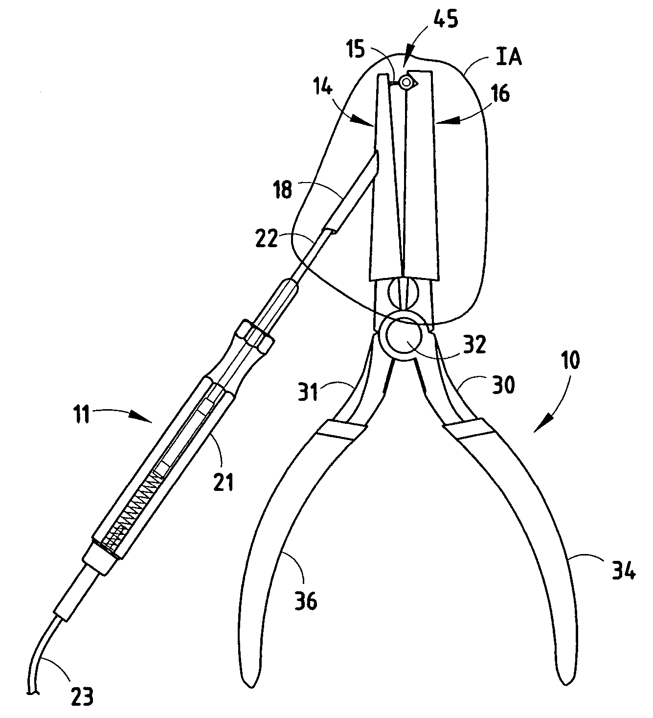
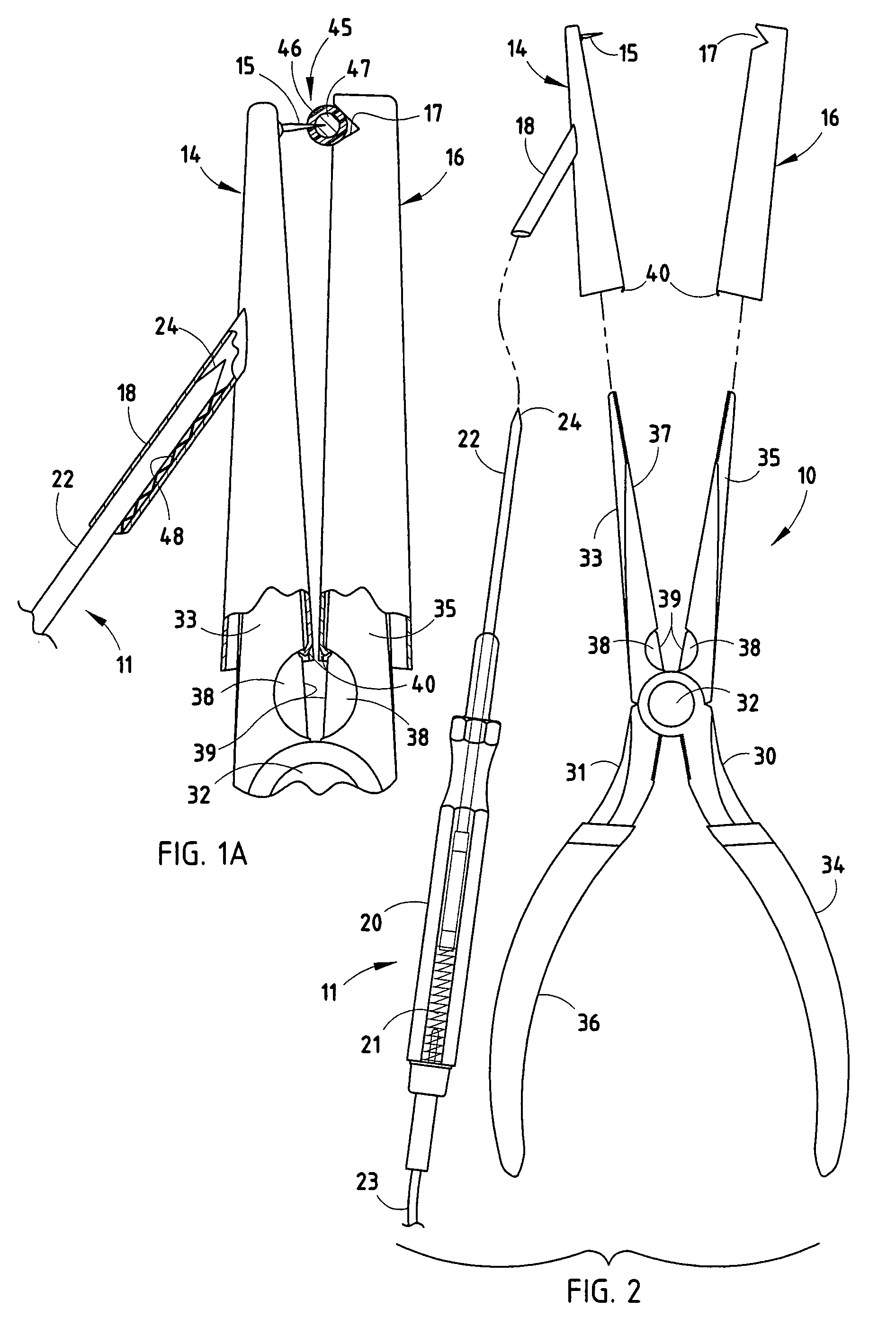
[0016] A kit (FIGS. 1-2) is provided for making a continuity tester from an existing pliers tool 10 and an existing continuity tester 11 (also called a “continuity checker” herein) to check electrical continuity of a wire 45. The kit includes a first sleeve 14 adapted to slip onto a free end of the first jaw and which includes a protrusion 15 that faces laterally, and a second sleeve 16 adapted to slip onto the second jaw and which includes a pocket 17 for holding the wire 45 while the protrusion is piercing the insulating cover 46 of the wire 45 and making contact with the conductor 47 inside the wire 45. The first and second sleeves 14 and 16 are tubular, and are held on by resilient tabs that frictionally engage the jaws. A tubular universal connector 18 adapted to receive and frictionally engage the probe of the continuity checker is provided either on the first sleeve 14 (or alternatively is provided on a third sleeve engageable with the first handle of the pliers tool 10 (see ...


PUM


Abstract

A kit is provided for making a continuity tester from an existing pliers tool and an existing continuity checker to check electrical continuity of a wire. The kit includes a first sleeve adapted to slip onto a free end of a first jaw of the pliers tool and which includes a protrusion that faces laterally, and a second sleeve adapted to slip onto a second jaw and which includes a pocket for holding the wire while the protrusion is piercing the wire. The first and second sleeves are tubular, and are held on by resilient tabs that frictionally engage the jaws. A connector adapted to frictionally engage the probe of the continuity checker is provided either on the first sleeve or on a third sleeve engagable with the first handle of the pliers tool. In one form, the kit is factory-installed as a permanent part of the pliers tool.

Description

BACKGROUND [0001] The present invention relates to continuity testers for testing electrical continuity of wires, and more particularly relates to a continuity tester made for use with existing equipment commonly owned by repairmen, such as a continuity tester having an elongated probe with pointed end and with a pair of needle nose pliers. [0002] Modern vehicles and crafts incorporate a large number of wires, which sometimes short out and require repair. A major part of the repair task is to check continuity to determine which wire is the problem and where the problem has occurred. The repair problem is compounded by the fact that the wires are often tucked into cramped corners and crevices where they are difficult to see and reach. Further, the testing equipment required for doing such testing is undesirably expensive, adding to the cost and frustrations of fixing the problem. Hence, repairmen need a simple continuity tester that can be manipulated and operated with one hand, and ...

Claims


Application Information

Patent Timeline
IPC IPC(8): G01R1/04G01R31/02
CPCG01R31/025G01R1/0425G01R31/52G01R31/54
Inventor FESSENDEN, FRED
Owner FESSENDEN FRED
Learn More