
Simple faucet water-filtering device

a water filter and faucet technology, applied in the direction of moving filter element filters, filtration separation, separation processes, etc., can solve the problems of water filter not meeting the safe water quality standard, water filter cannot be replaced, water filter cannot be effectively removed from etc., to achieve simple structure, effective removal of toxic materials and odors in water, and easy replacement

Inactive Publication Date: 2005-04-07
CHANG CHIN CHING
View PDF7 Cites 48 Cited by
  • Summary
  • Abstract
  • Description
  • Claims
  • Application Information

AI Technical Summary

Benefits of technology

[0006] It is therefore a primary object of the present invention to provide a simple faucet water-filtering device having simplified structure. The faucet water-filtering device can effectively remove toxic materials and odors contained in the water. After a period of use, the filtering material can be easily replaced. Therefore, the faucet water-filtering device can be reused without wasting resource.
[0007] It is a further object of the present invention to provide the above faucet water-filtering device in which the connecting section can be more firmly connected with a faucet without easily detaching therefrom.

Problems solved by technology

The fine metal mesh of the above faucet water filter can only filter off the larger particles entrained by the water, while failing to remove toxic materials contained in the water.
Therefore, such water filter cannot meet the standard of safe water quality.
Moreover, after a period of use of such water filter, some problems will take place and lead to inconvenience in use.
However, it is relatively complicated to process and assemble the above structure.
Also, it is too troublesome to maintain and replace the components of such water filters.
After a period of use, the rubber fitting ring and the binding ring will also elastically fail.
However, the tap water may flow back and spill.

Method used


Image

  • Simple faucet water-filtering device
  • Simple faucet water-filtering device
  • Simple faucet water-filtering device

Examples


Embodiment Construction

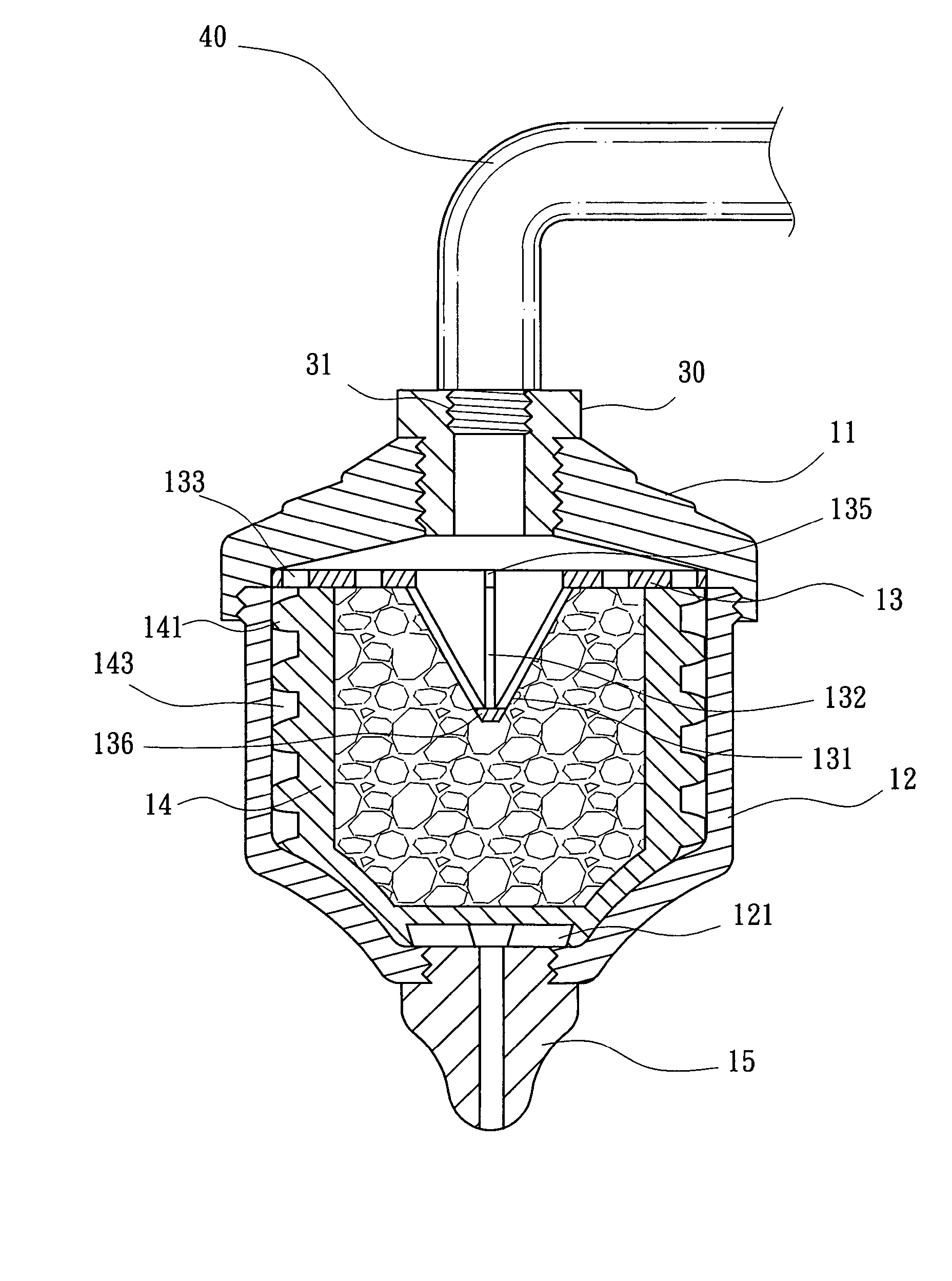
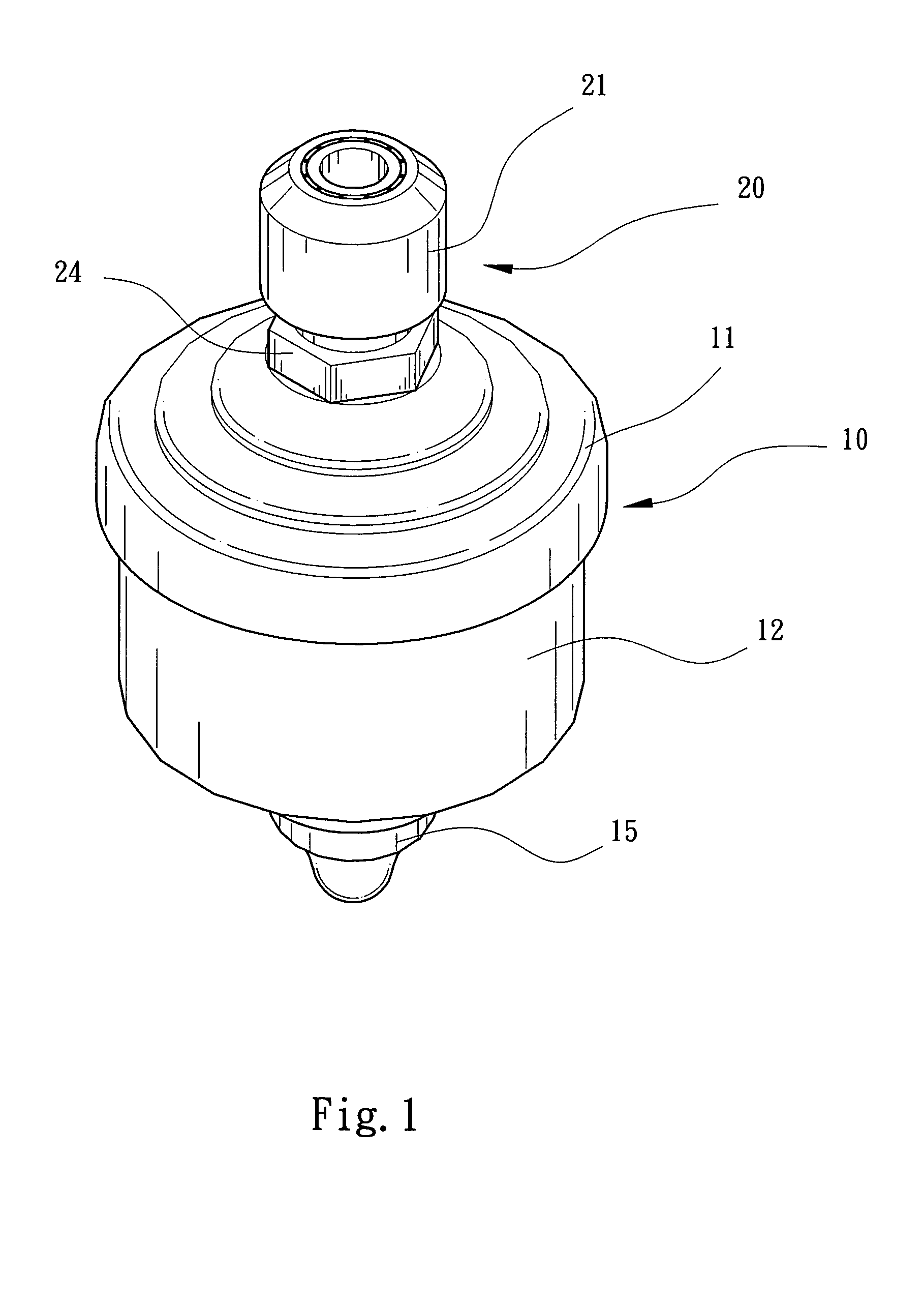
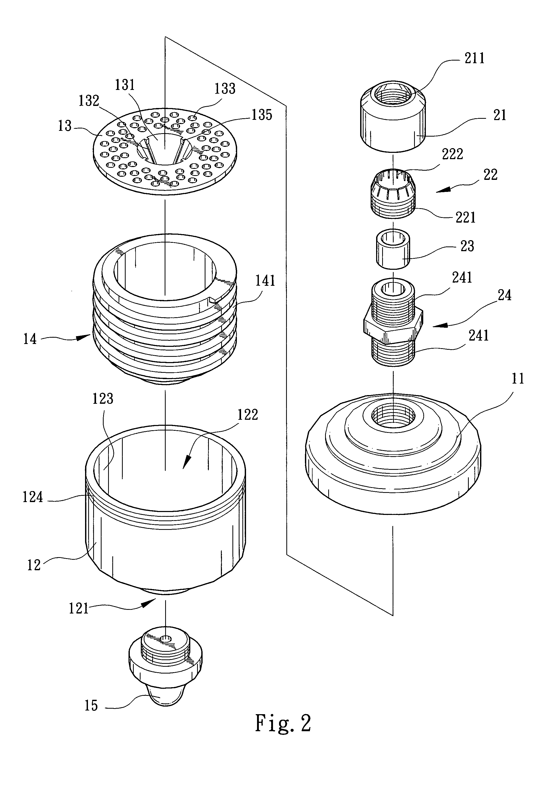
[0020] Please refer to FIGS. 1 and 2. The simple faucet water-filtering device of the present invention includes a main body 10 and a connecting section 20. An upper end of the connecting section 20 is connected with a spout of a faucet 40. A lower end of the connecting section 20 is screwed with an upper cap 11 of the main body 10. A lower end of the main body 10 is formed with a water outlet 121. The main body 10 is composed of the upper cap 11, a casing 12, a flow-conducting screen cover 13, an energy cup 14 and a water discharging connector 15. The casing 12 defines therein a receiving space 122 in which the energy cup 14 is placed. The outer wall of the energy cup 14 is formed with a spiral path 141, whereby a spiral water way 143 is defined between the outer wall of the energy cup 14 and the inner wall 123 of the receiving space 122. After flowing through the spiral water way 143, the water flows out from the water outlet 121 of the bottom of the casing 10.

[0021] The connecti...


PUM

PropertyMeasurementUnit
fastening forceaaaaaaaaaa
speedaaaaaaaaaa
energyaaaaaaaaaa

Abstract

A simple faucet water-filtering device including a main body and a connecting section. An upper end of the connecting section is adapted to connect with a spout of a faucet. A lower end of the connecting section is screwed with an upper cap of the main body. A lower end of the main body is formed with a water outlet. The main body has a casing defining a receiving space in which an energy cup is placed. An outer wall of the energy cup is formed with a spiral path, whereby a spiral water way is defined between the outer wall of the energy cup and inner wall of the receiving space. The water flows through the spiral water way and then flows out from the water outlet. The connecting section includes a faucet locking collar and an inner locking collar. The faucet locking collar has an inner conic opening at upper end. An upper end of the inner locking collar is formed with a conic section adapted to the inner conic opening of the faucet locking collar. An inner bushing is fitted in the inner locking collar.

Description

BACKGROUND OF THE INVENTION [0001] The present invention is related to a simple faucet water-filtering device having simplified structure. The faucet water-filtering device can be quickly firmly fitted with a faucet for purifying tap water. [0002] Taiwanese Utility Model Patent Publication No. 122700 discloses a faucet water filter. The water filter includes a main body which can smoothen the water flow and filter the water. The main body is funnel-shaped and has two openings at two ends. A fine metal mesh is disposed at the center of the main body. A rubber washer is fixed at the top opening for fitting with the faucet. By means of the fastening force of the rubber washer, the tap water is prevented from flowing back. [0003] The fine metal mesh of the above faucet water filter can only filter off the larger particles entrained by the water, while failing to remove toxic materials contained in the water. Therefore, such water filter cannot meet the standard of safe water quality. Mo...

Claims


Application Information

Patent Timeline
Patent Type & Authority Applications(United States)
IPC IPC(8): B01D35/04E03C1/04E03C1/08
CPCB01D35/046E03C2201/40E03C1/08E03C1/0404Y10T137/9464
Inventor CHANG, CHIN- CHING
Owner CHANG CHIN CHING
Learn More