
Sputter target having modified surface texture

Inactive Publication Date: 2005-04-07
HERAEUS INC
View PDF41 Cites 14 Cited by
  • Summary
  • Abstract
  • Description
  • Claims
  • Application Information

AI Technical Summary

Benefits of technology

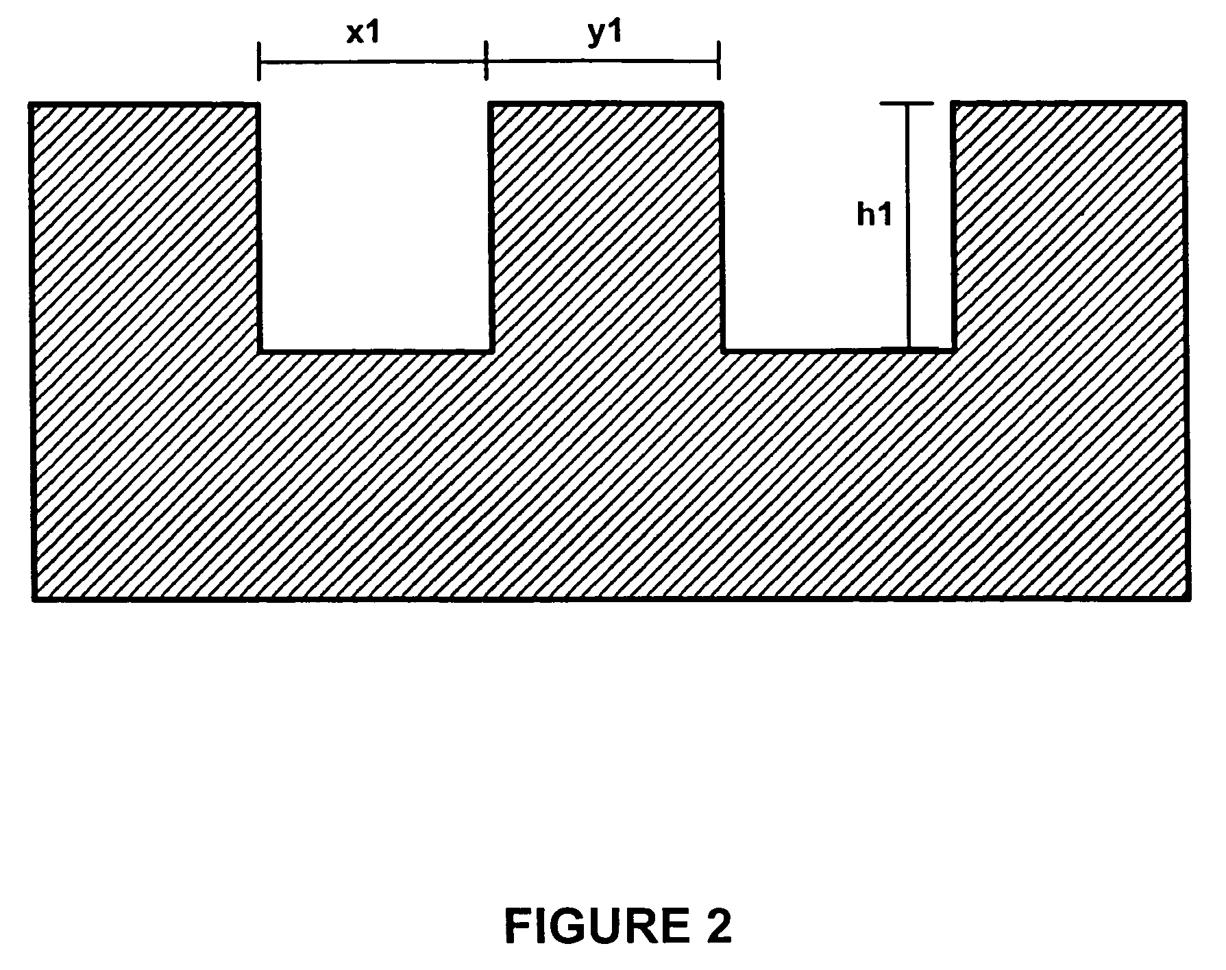
[0007] The present invention addresses the needs discuss above by modifying the surface texture of the sputter target. Specifically, the present invention macroscopically roughens the non-sputter areas of the sputter target to improve the ability of the non-sputter areas to trap re-deposited target coating material and reduce the effects of sputter re-deposition in sputtering applications.
[0009] According to other aspects of the invention, the macroscopic trough pattern in the non-sputter areas is microscopically roughened using conventional bead or grit blasting techniques. The microscopic roughening further improves the ability to trap re-deposited target coating material and prevent it from contaminating the film applied to the substrate.
[0010] In another aspect of the invention, the non-sputter areas are counter-bored into the face of the sputter target in addition to having the macroscopic trough patterns formed in them. Counter-boring the non-sputter areas places them farther away from the plasma environment than the sputter areas and further reduces the chances of re-deposited target coating material dislodging and contaminating the film applied to the substrate.

Problems solved by technology

Counter-boring the non-sputter areas places them farther away from the plasma environment than the sputter areas and further reduces the chances of re-deposited target coating material dislodging and contaminating the film applied to the substrate.

Method used


Image

  • Sputter target having modified surface texture
  • Sputter target having modified surface texture
  • Sputter target having modified surface texture

Examples


Embodiment Construction

[0016] The present invention concerns the modification of the surface texture of sputter targets to minimize the effects associated with sputter re-deposition. Sputter targets are made of a wide variety of materials which depend on the applications in which the sputtering is being used. As one skilled in the art will recognize, the invention described below does not depend on the material of the sputter target and can be applied to sputter targets in general. Accordingly, specific target materials are not mentioned in the description below.

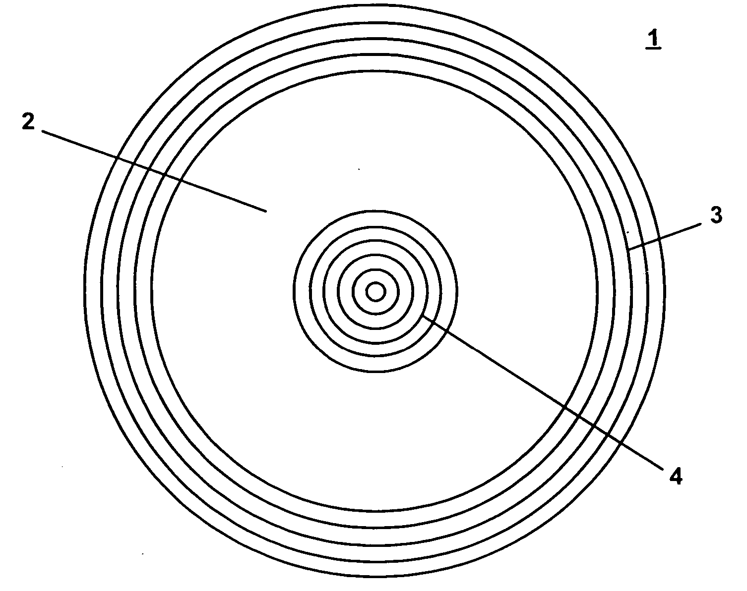
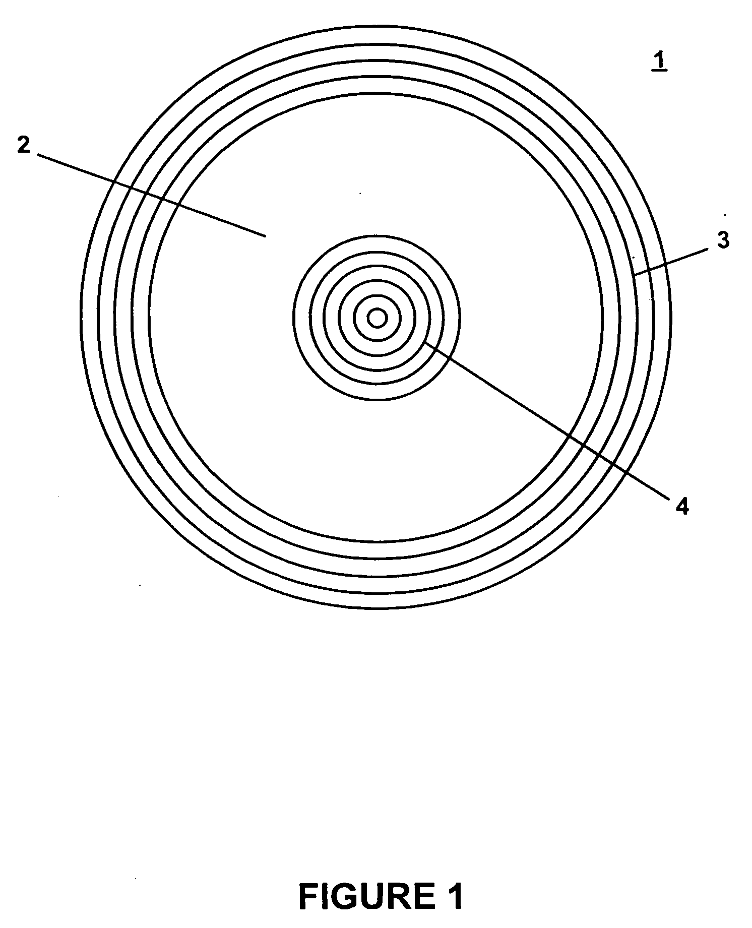
[0017]FIG. 1 is a diagram depicting the face of a sputter target according to one embodiment of the invention. As shown in FIG. 1, the face of sputter target 1 includes sputter area 2, and non-sputter areas 3 and 4. This embodiment of the invention is being described using a circular sputter target having one sputter area surrounding by a non-sputter area in the center of the target and a non-sputter area on the perimeter of the target. The inven...


PUM

PropertyMeasurementUnit
Areaaaaaaaaaaa

Abstract

The effects of sputter re-deposition are reduced by macroscopically roughening the non-sputter areas of the sputter target. The macroscopic roughening is obtained by forming a macroscopic trough pattern in the non-sputter areas of the sputter target. A variety of patterns may be used for the trough pattern. In addition to macroscopically roughing the non-sputter areas of the sputter target, microscopic roughening of the trough patterns may be performed using conventional shot, bead or grit blasting techniques.

Description

[0001] This application claims the benefit of U.S. Provisional Application No. 60 / 508,317, filed Oct. 6, 2003, which is hereby incorporated by reference.FIELD OF THE INVENTION [0002] The present invention relates to sputter targets used in physical vapor deposition processes, and more particularly relates to sputter targets having surface textures modified to minimize the effects of sputter re-deposition. BACKGROUND OF THE INVENTION [0003] Physical vapor deposition (PVD) techniques, such as sputtering, are used in a variety of fields to provide thin film material deposition of a precisely controlled thickness with an atomically smooth surface. In sputtering processes, a target located in a chamber filled with an inert gas atmosphere is exposed to an electric field to generate a plasma. Ions within this plasma collide with a surface of the sputter target causing the target to emit atoms from the target surface. A voltage difference between the target and the substrate that is to be c...

Claims


Application Information

Patent Timeline
IPC IPC(8): H01L21/203C23C14/34
CPCC23C14/3407H01J37/3491H01J37/3423
Inventor KENNEDY, STEVEN ROGERCHENG, YUANDA R.CORNO, PHILIP D.DARY, FRANCOIS
Owner HERAEUS INC
Learn More