
Microphone apparatus, noise reduction method and recording apparatus

a technology of microphone and recording device, applied in the direction of transducer details, instruments, electrical transducers, etc., can solve the problems of poor noise reduction performance, insatisfactory requirements of microphone units, and vibration dependent noise, so as to improve the converging characteristic of adaptive filters, reduce vibration and reduce nois

Inactive Publication Date: 2005-03-24
SONY CORP
View PDF9 Cites 120 Cited by
  • Summary
  • Abstract
  • Description
  • Claims
  • Application Information

AI Technical Summary

Benefits of technology

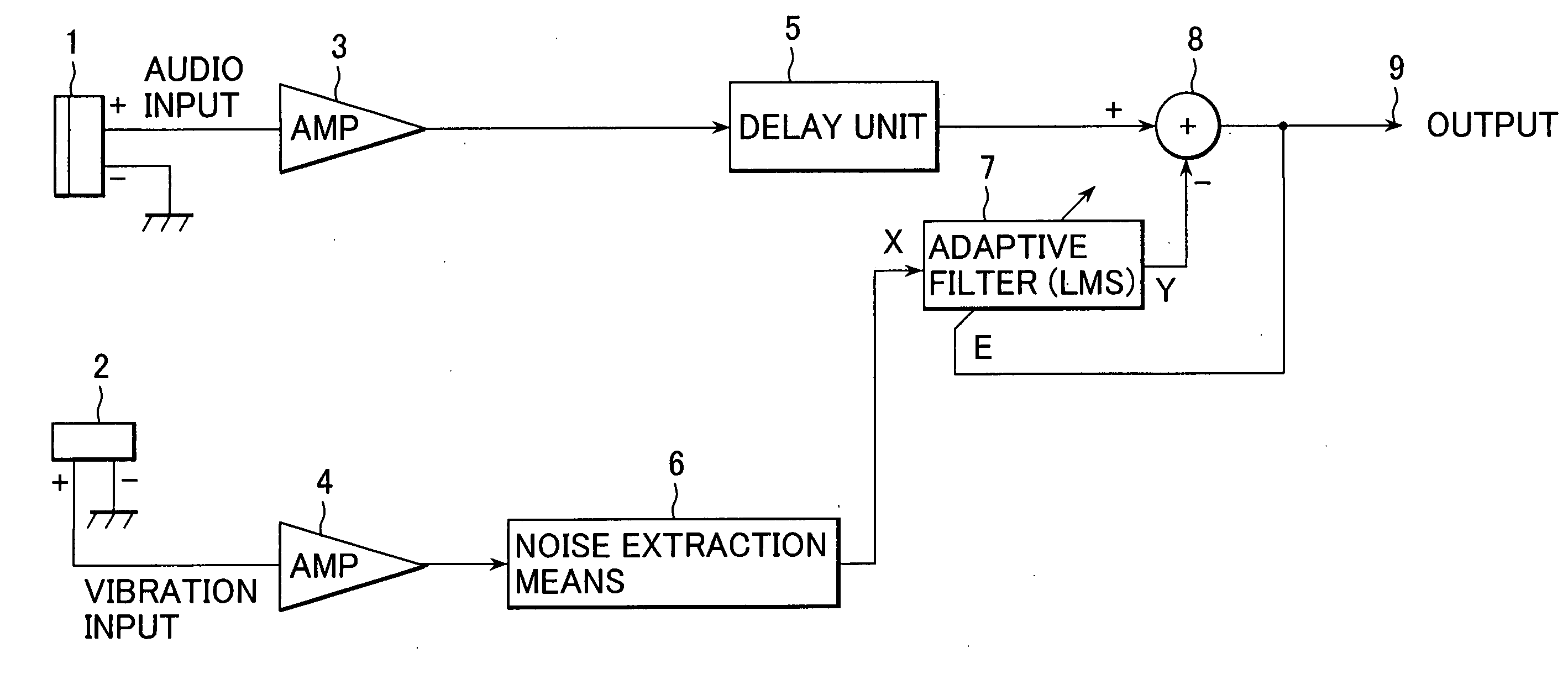
The present invention relates to a microphone apparatus that can effectively cancel out vibration dependent noise from an audio signal, even in cases where the microphone and sensor are not placed in an opposed relationship. The invention achieves this by using a vibration sensor and an adaptive filter that receives the output signal of the sensor as a reference input signal. The noise reduction performance of the invention is improved compared to existing techniques. Additionally, the invention allows for the use of a plurality of microphone units and a vibration sensor to accurately pick up and use only the target vibration noise.

Problems solved by technology

As a result, some problems arise in cases where requirements of the microphone units as described in Japanese patent application No. 2002-367234 are not satisfied, such as when a directional microphone unit like a unidirectional microphone or the like is used, in monaural microphone apparatus employing a single microphone unit, in apparatus of such construction as employing microphones disposed far apart with considerable distance therebetween, and the like.
H8-272377 discloses a technique to detect by sensor a signal having high correlation to noise which is to be rejected, and to generate a cancellation signal for reducing the noise by an adaptive filter based on the detected signal, its noise reduction performance is poor.

Method used


Image

  • Microphone apparatus, noise reduction method and recording apparatus
  • Microphone apparatus, noise reduction method and recording apparatus
  • Microphone apparatus, noise reduction method and recording apparatus

Examples


third embodiment

Now, description will be made hereunder on a fourth example of the microphone apparatus according to another preferred embodiment of the present invention as shown in FIG. 11. It is to be noted that the same reference numbers are used herein to refer to the same mechanism blocks as those in the third embodiment as shown in FIG. 10 and description will be made on only difference function blocks.

Firstly, FIG. 11 differs from the embodiment as shown in FIG. 10 in that the ON signal of the comparator 67 is connected to switches SW 79, 80. By selectively connecting movable contacts a to either fixed contacts b or c, the switches SW 79, 80 enable to select either output after or before performing noise reduction processing for each of the Lch and Rch. At the time when the ON signal is outputted, the movable contact is connected to the fixed contact c for outputting the noise reduced output from the Rch terminal 77 and the Lch terminal 78. On the other hand, at the time when the OFF signa...


PUM


Abstract

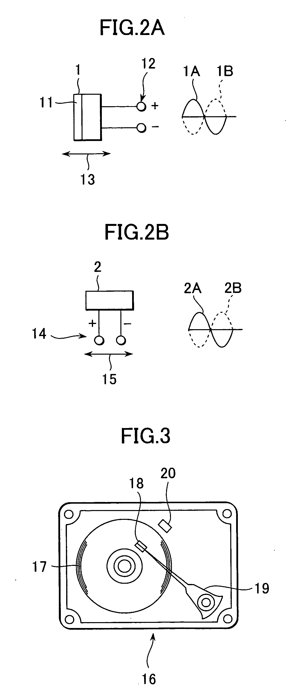
To achieve vibration-dependent noise reduction by the use of a microphone to pick up an audio signal and a vibration sensor. The microphone apparatus according to a preferred embodiment of the present invention is one having one or more microphone, one or more sensor, noise extraction means for extracting the noise bandwidth section from the output signal of the sensor, an adaptive filter coordinated with the microphone for receiving the output signal of the noise extraction means as the reference input signal, and an adder for subtracting the output signal of the adaptive filter from the output signal of the microphone, wherein the vibration detection directions of the microphone and the sensor match, and so do the output polarities of the vibration signal.

Description

CROSS REFERENCE TO RELATED APPLICATIONS The present document is based on Japanese Priority Application JP2003-285294 filed in the Japanese Patent Office on Aug. 1, 2003, the content in which being incorporated herein by reference to the extent permitted by law. BACKGROUND OF THE INVENTION 1. Field of the Invention The present invention relates to a microphone apparatus and a noise reduction method which are suitable for use in recording apparatus having a built-in camera, for example. 2. Description of the Related Art The applicant of this patent application has proposed in an earlier patent application, Japanese Application Publication No. 2002-367234, a microphone apparatus and a vibration-dependent noise reduction method and apparatus having a plurality of microphone units which are disposed in opposed relationship. This is a so-called sensorless noise reduction technique because a microphone to pick-up an audio signal is also used as a vibration sensor. However, the microp...

Claims


Application Information

Patent Timeline
Patent Type & Authority Applications(United States)
IPC IPC(8): G10K11/16G10K11/178H04R3/00
CPCH04R3/005G10K11/178G10K2210/1051
Inventor OZAWA, KAZUHIKO
Owner SONY CORP
Learn More