
Method and apparatus for controlling a stand-alone 4-leg voltage source inverter

a voltage source inverter, stand-alone technology, applied in the direction of electric variable regulation, process and machine control, instruments, etc., can solve the problems of insufficient compensation of high frequency harmonic distortion, inability of inverter control system to compensate for undesirable harmonics, and adverse effects on output power quality

Active Publication Date: 2005-03-24
GM GLOBAL TECH OPERATIONS LLC
View PDF3 Cites 38 Cited by
  • Summary
  • Abstract
  • Description
  • Claims
  • Application Information

AI Technical Summary

Benefits of technology

[0016] g) providing the set of control inputs to the inverter to enable compensating regulation of the fundamental and imbalance characteristics of the multi-phase output of the inverter.

Problems solved by technology

That is, with an unbalanced load, the three-phase output currents from an inverter will generally not add up to zero, as they would in a 3-leg balanced load situation.
If a neutral is not used with an unbalanced load, voltage imbalances may occur at the load terminals, and the output power quality may be adversely affected.
The ability of an inverter control system to compensate for undesirable harmonics is generally limited by the bandwidth of the system voltage control loop, which may not be adequate for compensating high frequency harmonic distortion.
Therefore, harmonic compensation and transient response would be limited to frequencies within this range.
Moreover, the transient response characteristics of an inverter control system may also be limited by the overall execution time of the regulating loop software modules.
That is, the larger the number of software modules, the greater the execution time, and the slower the transient response.

Method used


Image

  • Method and apparatus for controlling a stand-alone 4-leg voltage source inverter
  • Method and apparatus for controlling a stand-alone 4-leg voltage source inverter
  • Method and apparatus for controlling a stand-alone 4-leg voltage source inverter

Examples


Embodiment Construction

[0027] The following detailed description is merely exemplary in nature and is not intended to limit the invention or the application and uses of the invention. Furthermore, there is no intention to be bound by any expressed or implied theory presented in the preceding technical field, background, brief summary or the following detailed description.

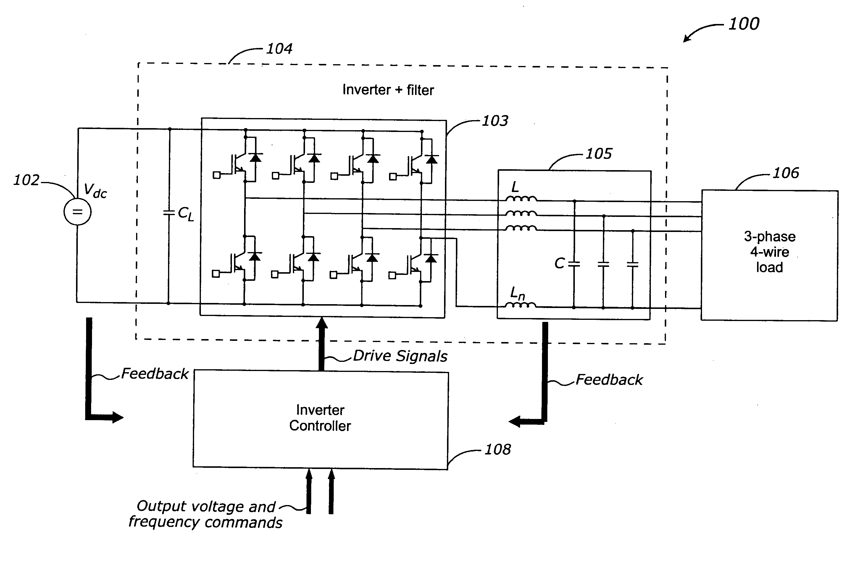
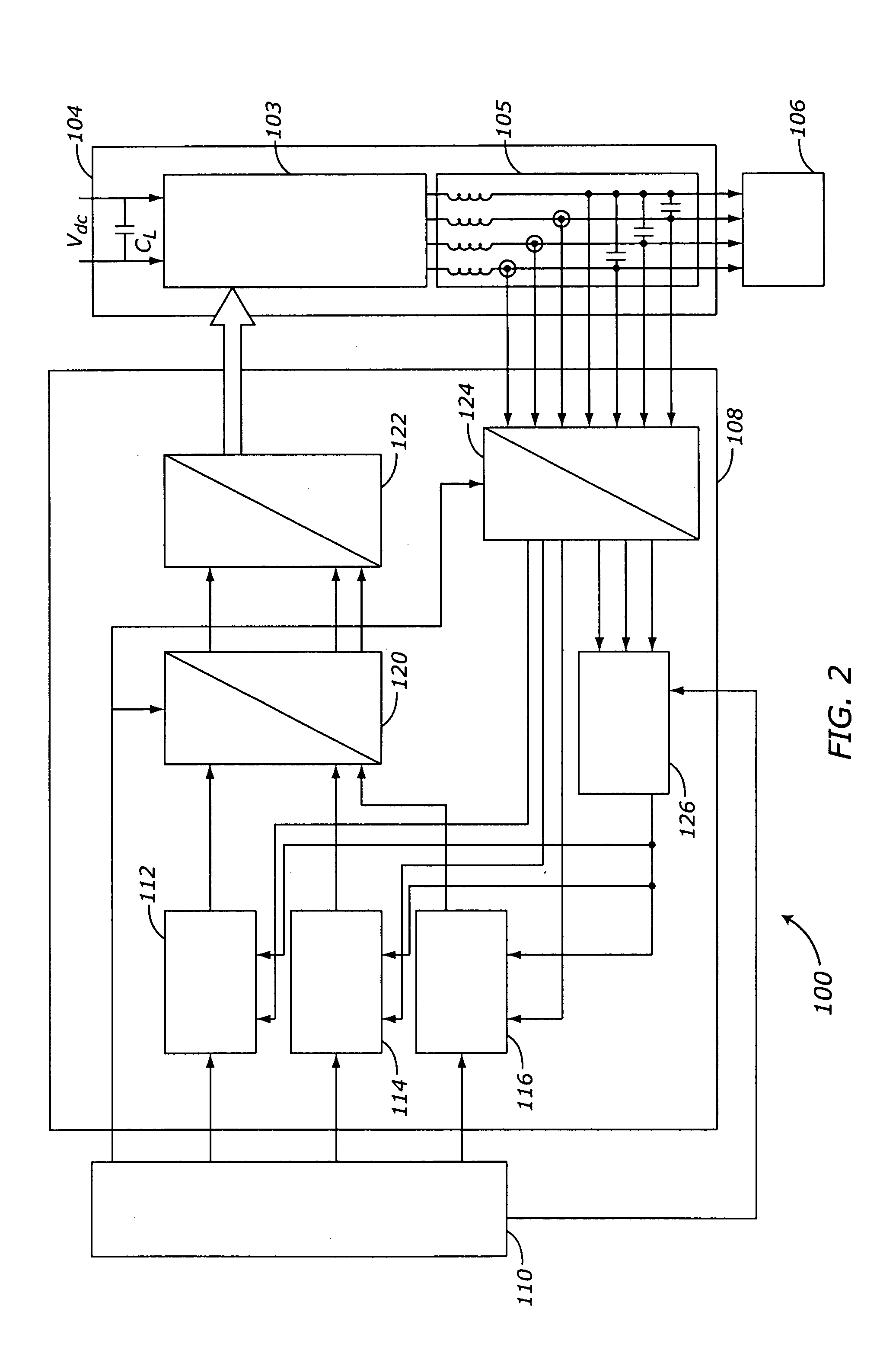
[0028] Various embodiments of the present invention pertain to the area of voltage source inverters operating in a stand-alone mode. Generally, this type of inverter is used to convert DC power available at a selected voltage into AC power with fixed voltage and frequency. Ideally, the output voltage and frequency stability of an inverter should be independent of load variations and imbalances. To provide this type of stabilization, an inverter controller may be used in a closed loop feedback configuration to provide regulating and imbalance compensating signals to the inverter. The inverter controller may be implemented in hardware or s...


PUM


Abstract

Methods and apparatus are provided for controlling a stand-alone four-leg three-phase inverter. The inverter three-phase output is converted from AC domain elements to corresponding DC domain elements. The DC domain elements are processed into combined regulating and imbalance compensating signals, including over-current limiting. The compensating signals are restored to corresponding AC domain signals, and are processed into control inputs for the inverter, in order to stabilize the inverter output when connected to an unbalanced load. The inverter controller can be implemented entirely in software as a control algorithm.

Description

TECHNICAL FIELD [0001] The present invention generally relates to three-phase voltage source inverters, and more particularly relates to the control of 4-leg three-phase voltage source inverters. BACKGROUND [0002] Three-phase voltage source inverters (VSI's) are generally used to convert DC power into three-phase AC power. Typically, the three-phase output voltages are sinusoidal waveforms spaced 120 degrees apart, to be compatible with a wide variety of applications requiring conventional AC power. In general, the output power frequencies commonly used are 50, 60, and 400 hertz, but other frequencies could be used as well. One current example of an inverter application is the electric or hybrid automobile, where a DC power source, such as a battery, fuel cell array, or other equivalent device, is converted into an AC power supply for various internal control functions, including the propulsion system. [0003] The quality of an inverter is generally determined by its output voltage a...

Claims


Application Information

Patent Timeline
Patent Type & Authority Applications(United States)
IPC IPC(8): H02M1/12H02M7/5387
CPCH02M7/53875Y10S323/908H02M2007/53876H02M7/53876
Inventor STANCU, CONSTANTIN C.HITI, SILVA
Owner GM GLOBAL TECH OPERATIONS LLC
Learn More