Molded plastic gangway

a molded plastic and gangway technology, applied in the field of gangways, can solve the problems of difficult removal of gangways, time-consuming and difficult assembly of gangways, and difficult security of gangways

Inactive Publication Date: 2005-03-24
E Z DOCK
View PDF27 Cites 5 Cited by
  • Summary
  • Abstract
  • Description
  • Claims
  • Application Information

AI Technical Summary

Benefits of technology

[0009] Two or more gangway sections can be connected together to form a gangway. Gangway sections can be connected using a reinforcing member or truss which is received in the gangway bottom surface trough. The truss is sized to extend across the junction between adjacent gangway sections. The truss is secured to the gangway sections by fasteners which extend through the gangway section upper surface and into the truss. The gangway sections can also be connected by use of connector plates which

Problems solved by technology

These gangways are time consuming and difficult to assemble.
Additionally, the gangways are difficult to secure, for example, to the dock

Method used


Image

  • Molded plastic gangway
  • Molded plastic gangway
  • Molded plastic gangway

Examples


Embodiment Construction

[0032] The following detailed description illustrates the invention by way of example and not by way of limitation. This description will clearly enable one skilled in the art to make and use the invention, and describes several embodiments, adaptations, variations, alternatives and uses of the invention, including what I presently believe is the best mode of carrying out the invention. Additionally, it is to be understood that the invention is not limited in its application to the details of construction and the arrangements of components set forth in the following description or illustrated in the drawings. The invention is capable of other embodiments and of being practiced or being carried out in various ways. Also, it is to be understood that the phraseology and terminology used herein is for the purpose of description and should not be regarded as limiting.

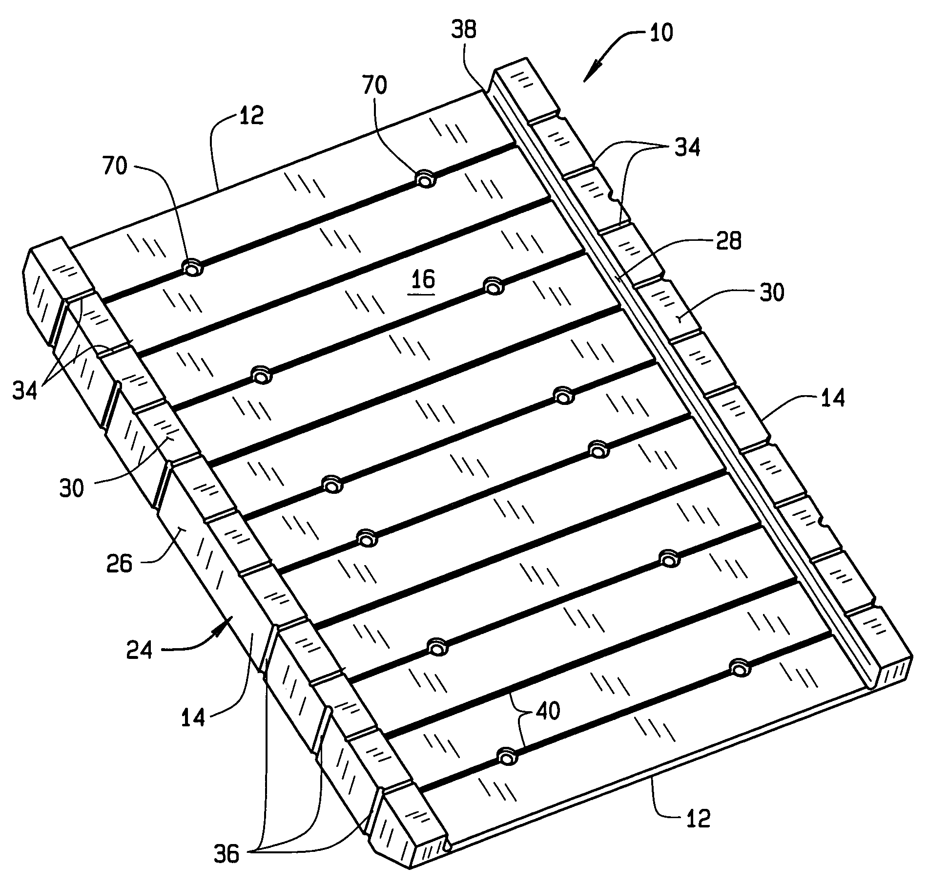
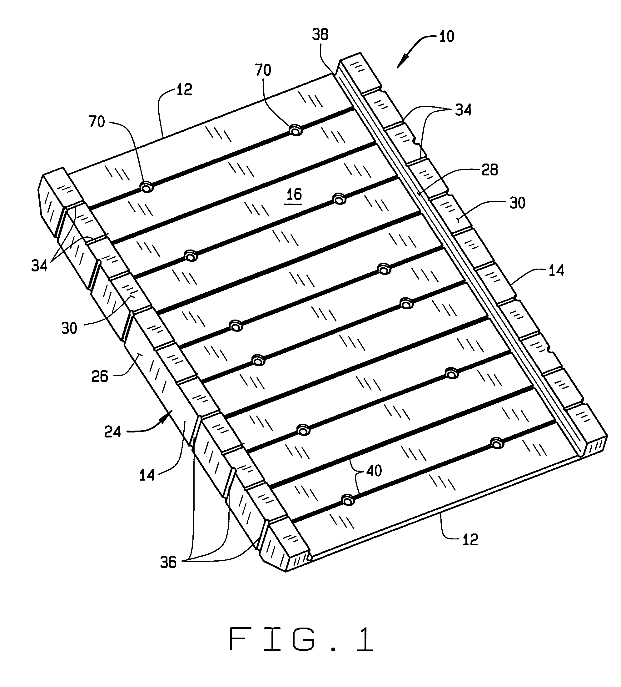
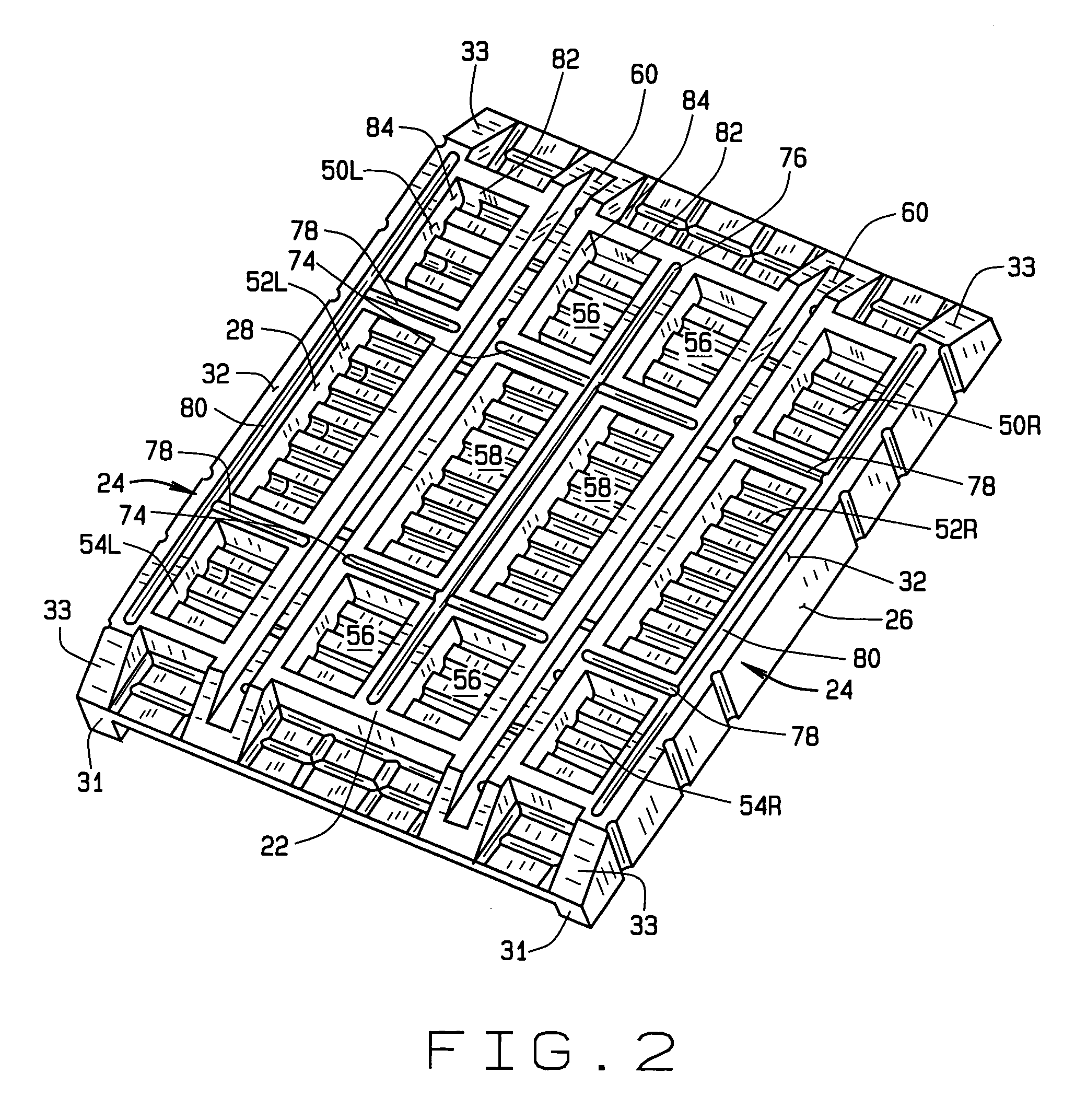
[0033] An illustrative embodiment of a gangway section 10 of the present invention is seen generally in FIGS. 1 and 2. A ...


PUM

PropertyMeasurementUnit
Timeaaaaaaaaaa
Lengthaaaaaaaaaa
Thicknessaaaaaaaaaa

Abstract

A molded gangway section is provided to form a gangway between a shore and a dock, pier, and the like. The gangway includes an upper tread surface and a bottom surface having recesses formed therein. The ceilings or upper surfaces of the recesses are formed with grooves. Two or more of the gangway sections can be connected together to form gangways of incrementally increasing lengths. Hinge connections are provided to connect the gangway to piers, docks, shore abutments, ramps, etc. Additionally, a roller can be mounted to a shore end of the gangway.

Description

CROSS-REFERENCE TO RELATED APPLICATIONS [0001] Not Applicable. STATEMENT REGARDING FEDERALLY SPONSORED RESEARCH OR DEVELOPMENT [0002] Not Applicable. BACKGROUND OF THE INVENTION [0003] This invention relates to gangways used for example with docks, piers, and the like, and in particular, to a gangway which is molded from plastic. [0004] Gangways have long been used to provide access between shore and docks, or between docks and boats. Gangways that are currently used are often one piece units that are assembled on-site. These gangways are time consuming and difficult to assemble. Additionally, the gangways are difficult to secure, for example, to the dock, a shore abutment, etc. Further, once assembled, the gangways are difficult to remove, for example, for storage in winter or for repair. BRIEF SUMMARY OF THE INVENTION [0005] Briefly stated, a molded gangway section of the present invention comprises an upper surface, side surfaces, and a lower surface, which, in combination define...

Claims


Application Information

Patent Timeline
IPC IPC(8): B63B27/14E02B3/06
CPCB63B27/14E02B3/064B63B2231/40E01D15/24E01D2101/40
Inventor OSTRENG, TROYMOODY, LARRY
Owner E Z DOCK
Why Eureka
Try Eureka