Exhaust volume measurement device

a measurement device and exhaust gas technology, applied in the direction of instruments, structural/machine measurement, chemical methods analysis, etc., can solve the problems of inaccuracy in emissions testing, large cvs system, calibration procedure, etc., and achieve the effect of accurate measurement of flow

Inactive Publication Date: 2005-03-24
AVL TEST SYST
View PDF14 Cites 7 Cited by
  • Summary
  • Abstract
  • Description
  • Claims
  • Application Information

AI Technical Summary

Benefits of technology

Accordingly, the above invention provides an exhaust volume measurement device that may be packaged within a cell while maintaining a homogeneous mixture and provides an accurate measurement of the flow.

Problems solved by technology

CVS systems are quite large and costly, especially when they are designed for large flow rates.
An additional requirement for vehicle testing is a low pressure change at the exit of the tailpipe, which can only be achieved with a low flow restriction of the flow metering device.
The pressure pulsations within the exhaust gases may introduce an error into the flow measurement and may result in an inaccuracy in the emissions test.
However, an inaccuracy results with such a calibration procedure because of the nonlinear relationship between the differential pressure across the subsonic venturi and the flow rate through this device.
Further, inaccuracies are caused in the temperature measurement from inhomogeneous mixing of make-up air and hot exhaust gases.

Method used


Image

  • Exhaust volume measurement device
  • Exhaust volume measurement device
  • Exhaust volume measurement device

Examples


Embodiment Construction

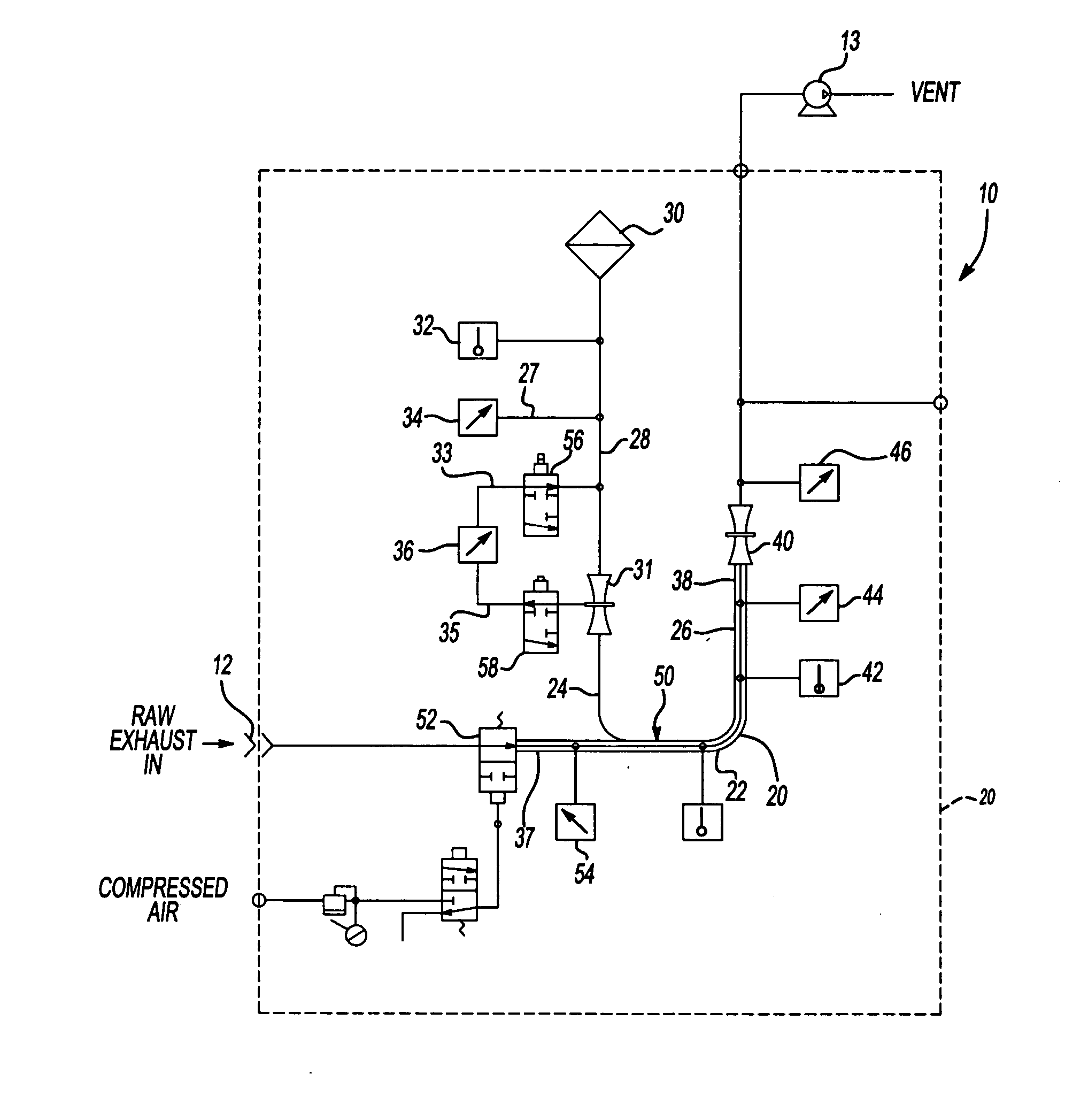
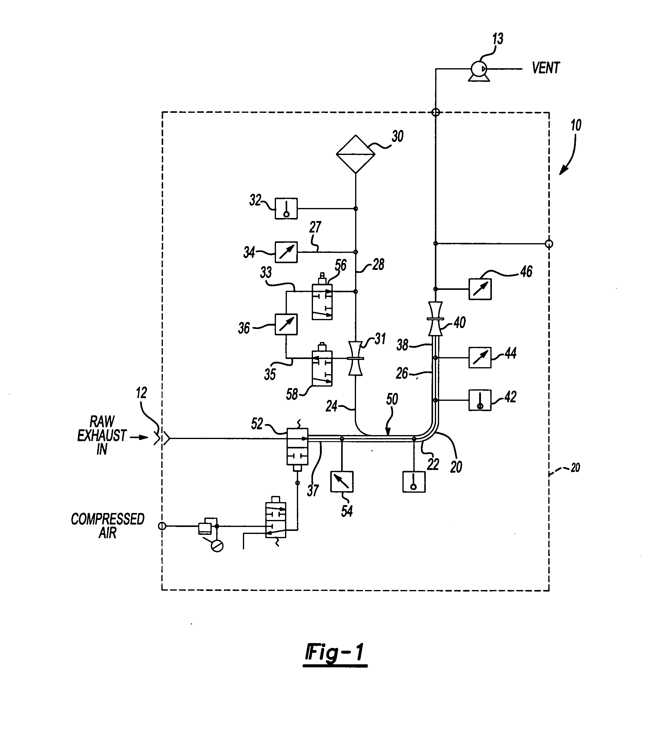
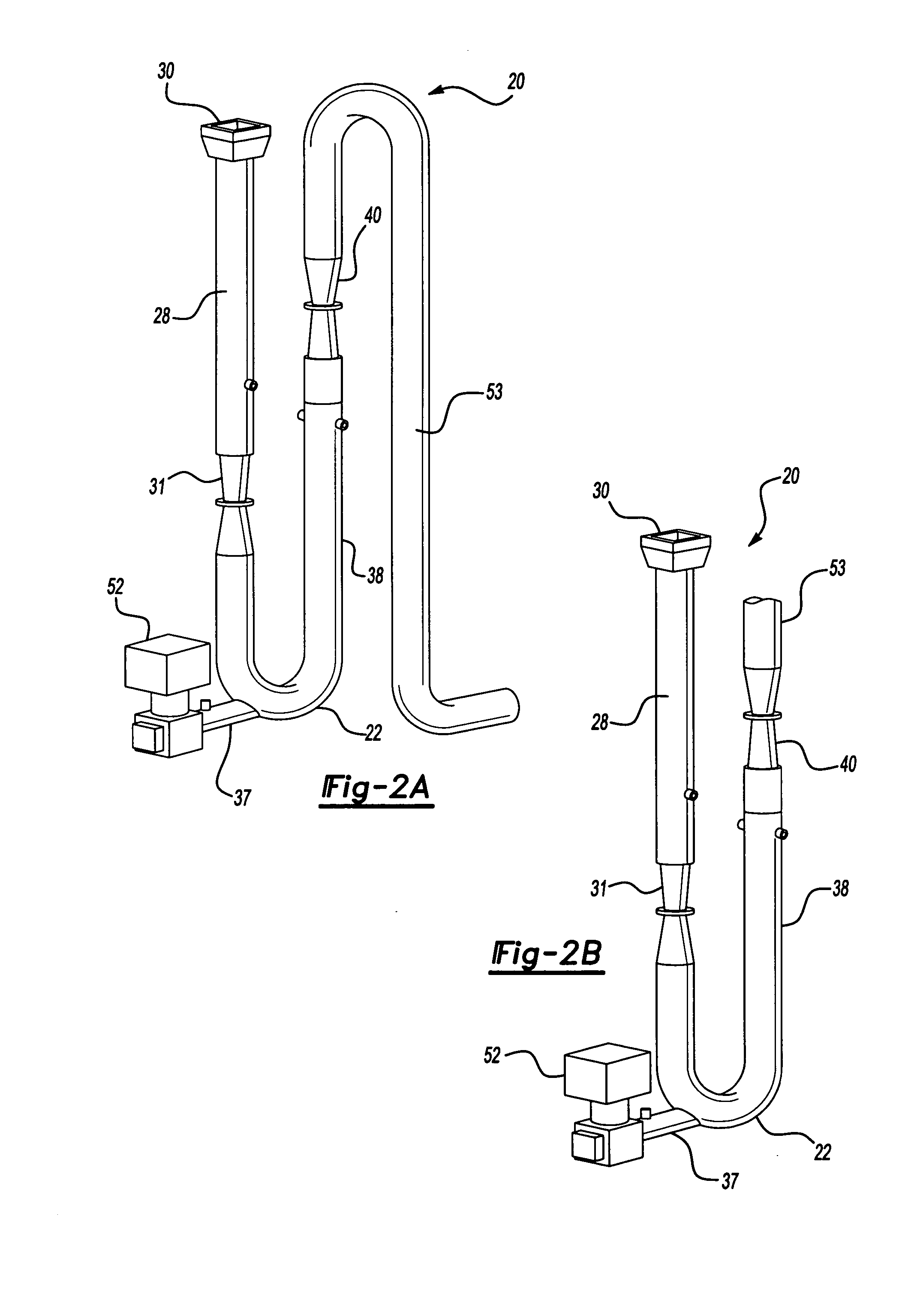
The exhaust flow measurement system 10 is shown schematically in FIG. 1. The system 10 is attached to a tailpipe 12 from an engine or vehicle that contains exhaust gases having the products of combustion. Since the flow measurement system 10 must typically be packaged within the spatial constraints of an emissions test cell, the tubing in the system must be arranged in such a manner to fit within the test cell. Similarly, it is desirable to have the flow measurement devices and sensors packaged compactly relative to one another so that they and the associated controllers may be packaged as a unit within the test cell along with the tubing.

The exhaust gases from the tailpipe 12 are mixed with a make-up gas such as ambient air. The flow of the exhaust (Qexaust) is determined by taking the total flow of the exhaust gases mixed with make-up air (Qtot) and subtracting the flow of the make-up air (Qair). The calculation without correction is represented by equation 1 below.

Qexaust=Qto...


PUM

PropertyMeasurementUnit
outer radiusaaaaaaaaaa
Constant Volume Samplingaaaaaaaaaa
homogenousaaaaaaaaaa

Abstract

A vehicle exhaust measurement system is provided includes that a conduit having a conduit inlet and a conduit outlet. A make-up air tube is connected to and is in fluid communication with the conduit inlet. The make-up air tube provides make-up air for mixing an exhaust gas. A mixed gas tube is connected to and is in fluid communication with the conduit outlet. The mixed gas tube conveys a mixture of make-up air and exhaust gas to analysis equipment. In the preferred embodiment, the exhaust gas tube extends through an outer wall of the conduit. A mixing plate is arranged in either the conduit or the mixed gas tube with the exhaust gas tube extending to a position adjacent to the mixing plate. The exhaust gas tube conveys the exhaust gas to the mixing plate to mix the exhaust gas and the make-up air at the mixing plate. A correction factor may be applied to the measurements taken by a differential pressure based fluid flow measurement device such as a smooth approach orifice (SAO) to provide an adjusted flow of measurement at the flow measurement device to correct for the pressure pulsations. The correction factor is calculated based upon the intensity of the pulsations of the differential pressure signal, which indicates the flow through the SAO.

Description

BACKGROUND OF THE INVENTION This invention relates to an engine or vehicle exhaust measurement device, and more particularly, the invention relates to a compact direct vehicle exhaust flow measurement device (DVE), which may be easily packaged within a test cell while providing compensation for engine exhaust pulsations when needed. The determination of engine or vehicle exhaust emissions during a test cycle is necessary to verify compliance with emission standards. To quantify the products of combustion correctly either the exhaust flow has to be known or an alternative method has to be used. A common method is the CVS (Constant Volume Sampling) principle, which has been used for many years in the industry and is a widely used standard. A CVS system samples the total amount of exhaust gas expelled by the engine or vehicle and dilutes it with air. The total flow as a sum of exhaust gas and dilution air is kept virtually constant. A constant sample is taken at a point far enough do...

Claims


Application Information

Patent Timeline
Patent Type & Authority Applications(United States)
IPC IPC(8): G01M15/10
CPCG01M15/102
Inventor SILVIS, WILLIAM MARTINKREFT, NORBERTMAREK, GERALDWILLIAMSON, JAMES
Owner AVL TEST SYST
Why Eureka
Try Eureka