
Press bending station for the bending of glass sheets

a technology of press bending and glass sheets, which is applied in the direction of glass rolling apparatus, glass tempering apparatus, manufacturing tools, etc., can solve the problems of glass sheet being incorrectly bending, dimensional change shape and size, optical distortion, cracking, breaking, etc., to prevent slippage, release the glass sheet during the press bending process, and the mold to be properly held

Active Publication Date: 2005-03-24
PILKINGTON AUTOMOTIVE DEUT GMBH +1
View PDF11 Cites 30 Cited by
  • Summary
  • Abstract
  • Description
  • Claims
  • Application Information

AI Technical Summary

Problems solved by technology

Otherwise, the bending process results in waste or products that possess poor quality.
Specifically, heat gained or lost by the glass sheet throughout the press bending process can cause the glass sheet to be incorrectly bent, to crack, break, optically distort, and / or dimensionally change shape and size.
Varying surface contours of the full-face mold can make it difficult for the mold to properly hold, position, prevent slippage of, and release the glass sheet during the press bending process.
A partial vacuum present at the mouths of the suction holes and slow execution of the bending process can produce in the glass sheet, as an unavoidable side-effect, local cooling zones which can impair the optical properties of the glass sheet at these points.
Molds and bending tools contacting the heated glass sheet can also induce physical or optical distortion of the product.
In addition, particulates originating from a variety of process or external sources can mar and distort the glass sheet surface during the bending process.
Also, it is still difficult to consistently and properly position, hold, and release the glass sheet at the mold surfaces, and to prevent slippage of the glass sheet during the press bending process.
Further, opposite mold surfaces place pressure on product viewing areas, which can result in the localized cooling that may lead to physical or optical distortion.

Method used


Image

  • Press bending station for the bending of glass sheets
  • Press bending station for the bending of glass sheets
  • Press bending station for the bending of glass sheets

Examples


Embodiment Construction

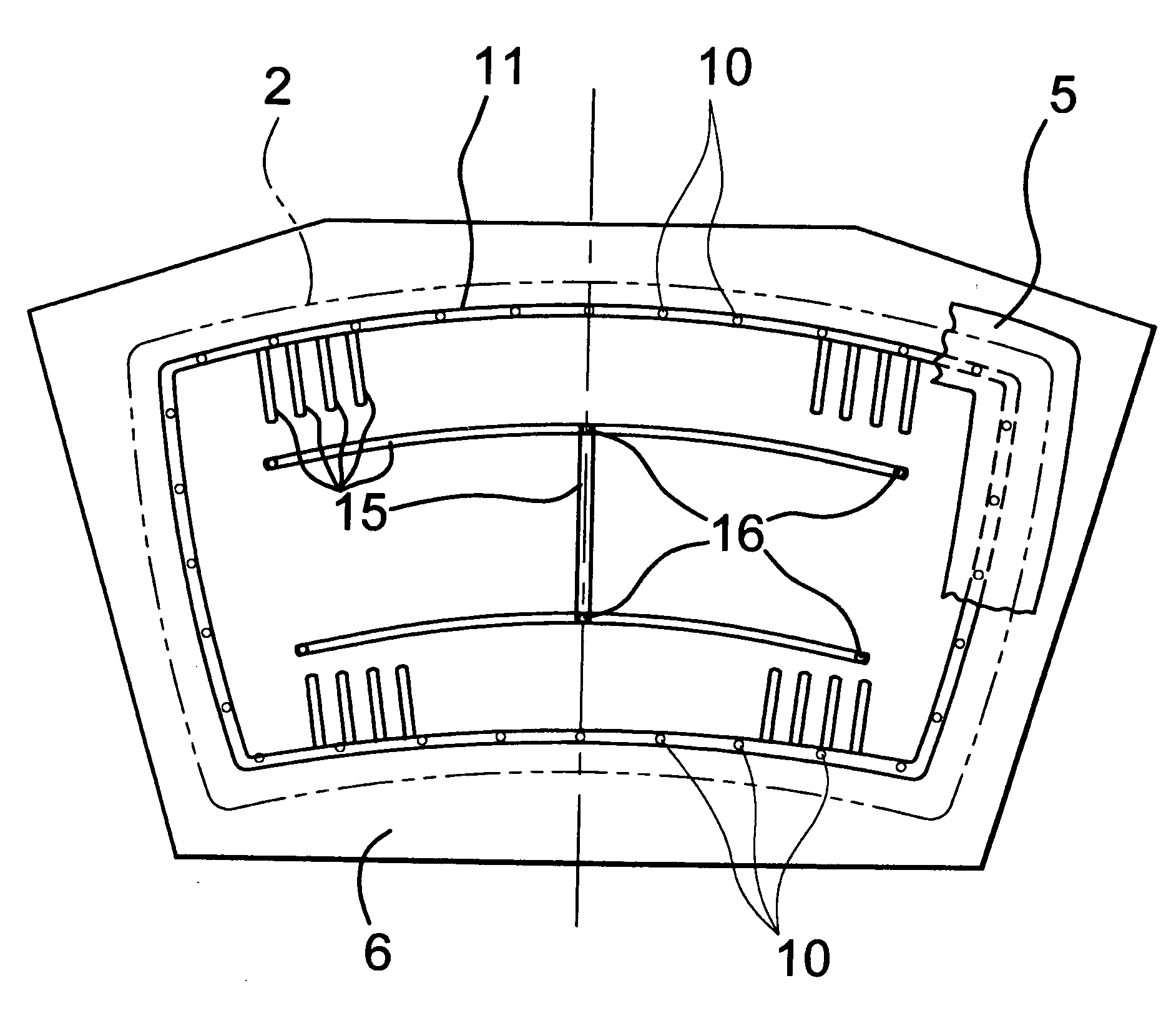
[0022] The invention provides a full-face mold that includes at least some holes arranged in at least one groove, which can have various cross-sectional shapes. The groove or grooves are formed in a molding face on a major surface of the full-face mold.

[0023] In addition, the holes may be connected to a source of positive or negative pressure. A particularly preferred form of the invention is characterized by the fact that a number of holes are connected together by at least one groove formed in the molding face of the full-face mold.

[0024] It has been shown that this relatively simple measure accelerates considerably the removal by negative pressure of the air between the molding face of the full-face mold and the glass sheet to be bent. The arrangement of holes in at least one groove means that a comparatively large volume of air can quickly be drawn away from the mold face, especially at the start of the removal by negative pressure, so that the glass sheet can lie substantiall...


PUM

PropertyMeasurementUnit
Lengthaaaaaaaaaa
Depthaaaaaaaaaa
Thicknessaaaaaaaaaa

Abstract

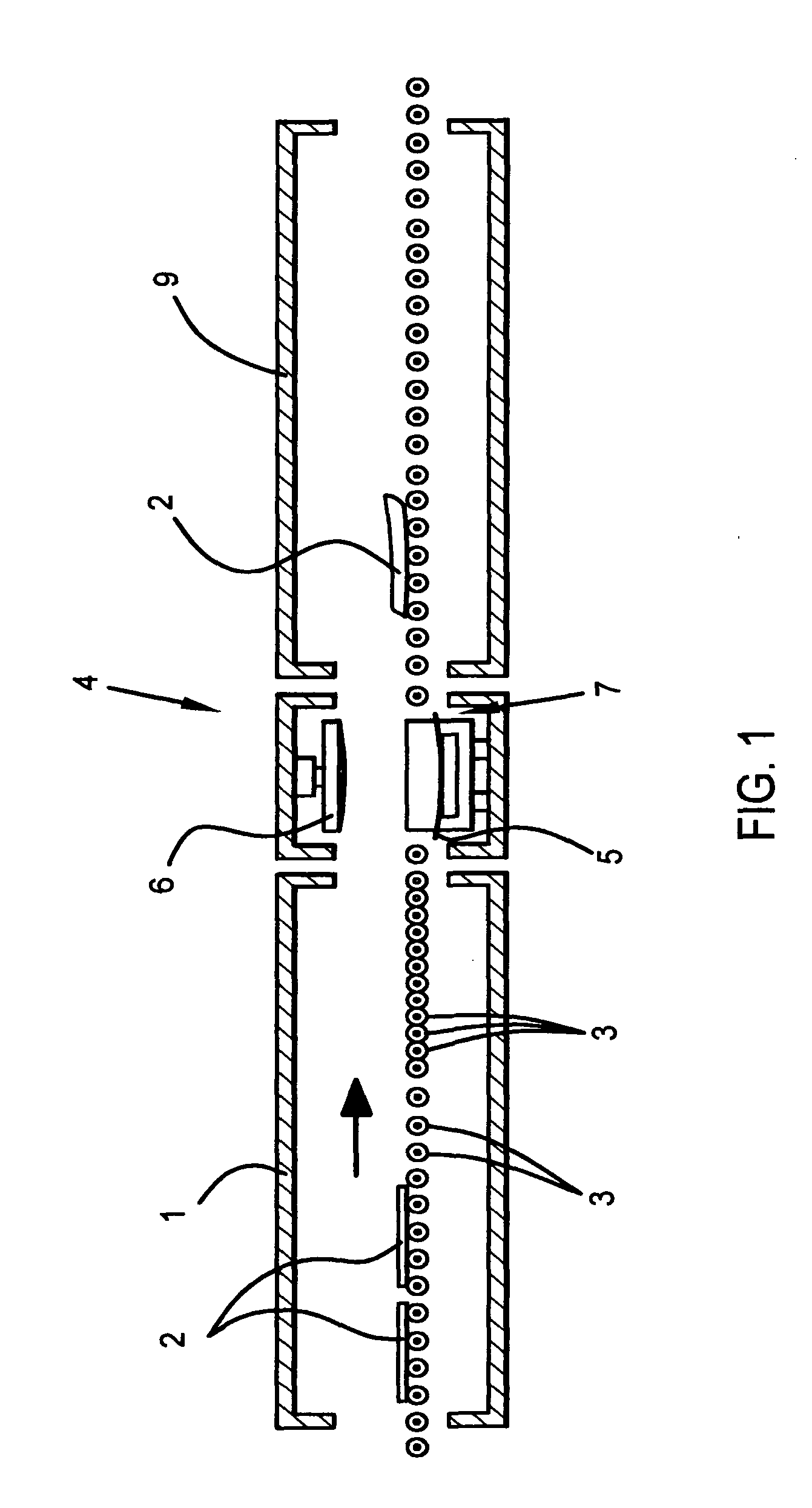
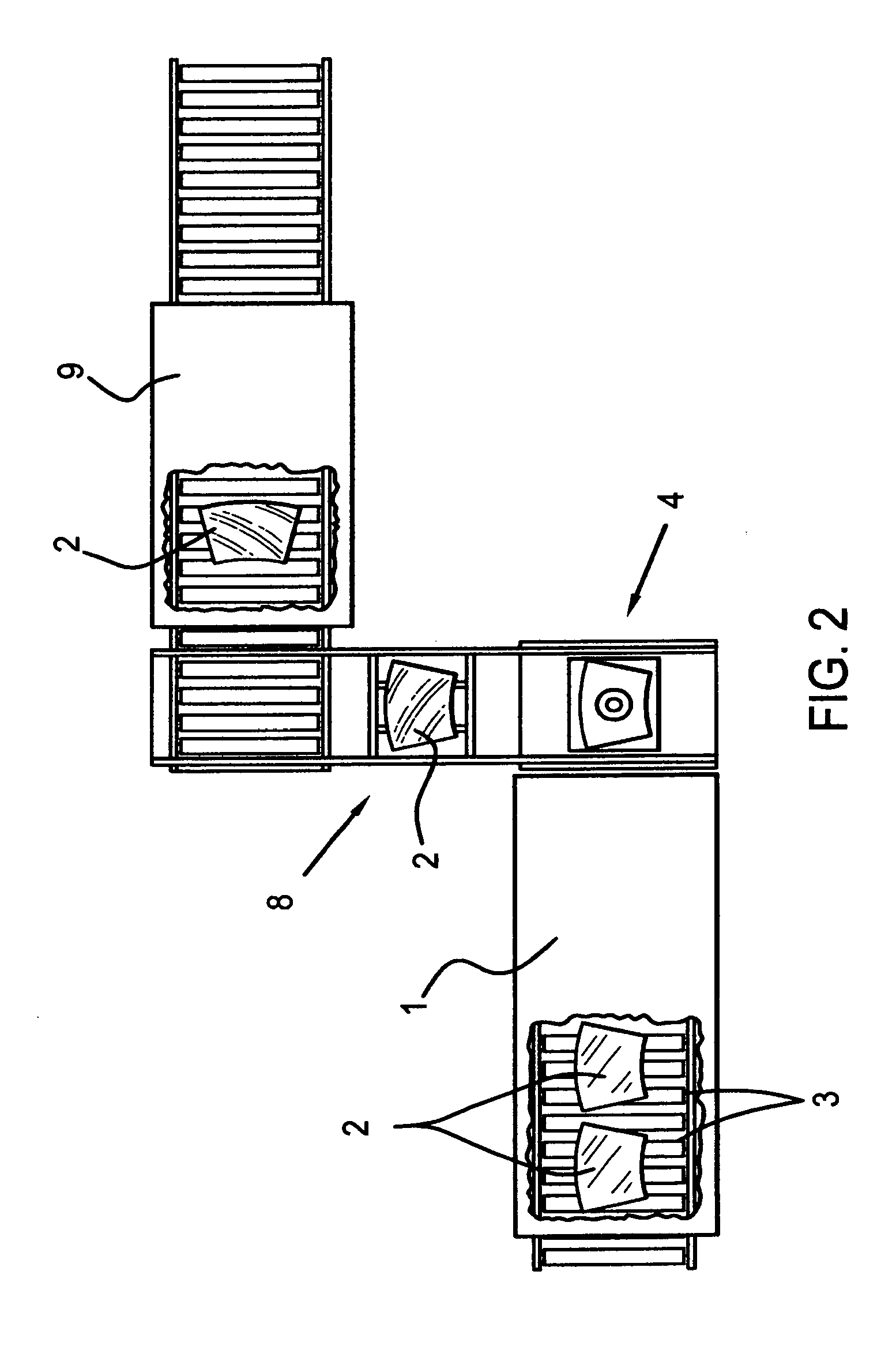
A press bending station includes an annular mold (5) and a full-face mold (6). Holes (10), selectively connected to a negative pressure source, are placed in portions of the full-face mold (6) that are determined by the configuration of the annular mold when the annular mold comes into contact with a heated glass sheet (2) during the press bending process. The sheet (2) is drawn by negative pressure through the holes (10) towards the full-face mold (6) and thus acquires its shape. Positive pressure may be selectively applied to the holes (10) to release the sheet (2). According to the invention, at least some of the holes (10) are arranged in at least one groove (11) formed in the mold face of the full-face mold. The grooves (11) according to the invention accelerate considerably the removal by negative pressure of the air between the molding face of the full-face mold (6) and the glass sheet (2) to be bent and thus improve the press bending process.

Description

BACKGROUND OF THE INVENTION [0001] The invention relates to press bending of heated materials, with opposing bending tools that are moved toward and away from each other. More particularly, the invention relates to a press bending station for the bending of heated glass sheets, with two bending tools that are moved toward one another. [0002] Typically, in press bending, an essentially solid male mold, also known as a full-faced mold, forms one bending tool, while the other bending tool is designed as an annular or ring-type female mold. Also, in order to aid in the bending process, a plurality of suction holes are placed in portions of the full-face mold that are determined by the configuration of the annular mold when the annular mold comes into contact with a heated glass sheet during the press bending process. [0003] As described, when a source of vacuum is applied to the male mold, the negative pressure created is transmitted through the mold via the suction holes thus causing t...

Claims


Application Information

Patent Timeline
IPC IPC(8): C03B23/03C03B23/035
CPCC03B23/03C03B40/005C03B23/0357C03B23/02C03B23/035
Inventor BOISSELLE, ROBERT J.FUNK, DIETERPILZ, JOACHIMGORGES, ANDREAS
Owner PILKINGTON AUTOMOTIVE DEUT GMBH
Learn More