
Flexible magnetic pad with multi-directional constantly alternating polarity zones

Inactive Publication Date: 2005-03-17
NYUU MAGUNETEIKUSU
View PDF32 Cites 4 Cited by
  • Summary
  • Abstract
  • Description
  • Claims
  • Application Information

AI Technical Summary

Benefits of technology

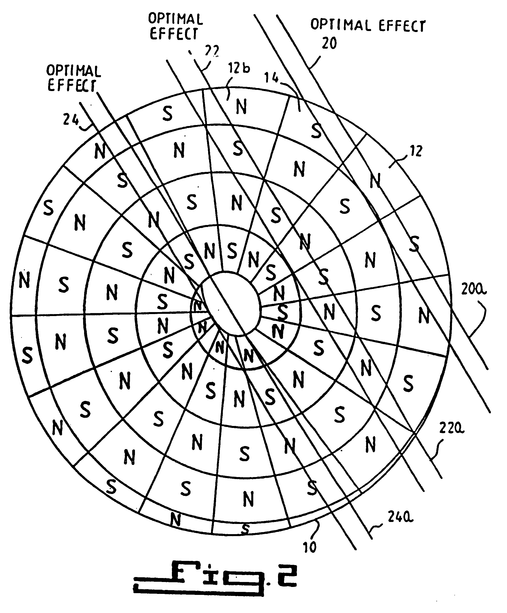
[0018] The device of the present invention utilizes principles set forth in the Latzke '711 patent. In the present invention, magnetic poles are arranged in an alternating pattern of north (−) and south (+) polarity zones or poles. When placed over an afflicted area of the human body, these polarity zones have been shown to have a therapeutic effect. For example, the pad can be applied to musculo-skeletal bruises, sore muscles and joint pain for relief to the user from such pain. These polarity zones, however, must be positioned in such a way as to cause blood moving through the veins in the body to pass through the magnetic fields established by the polarity zones in an alternating field pattern. This would easily be accomplished if all the blood vessels in the body were situated in the same direction. It is obvious, however, that this is not the case. The Latzke '711 device calls for the magnetic poles to be arranged in a parallel-striped configuration, as noted in FIG. 1 of Latzke '711 (as illustrated in FIGS. 3 and 4 herein). Therefore, its effectiveness is limited only to those blood vessels which cross the parallel boundaries of adjacent poles in a perpendicular or nearly perpendicular manner (as noted in FIG. 4 herein of the present invention).
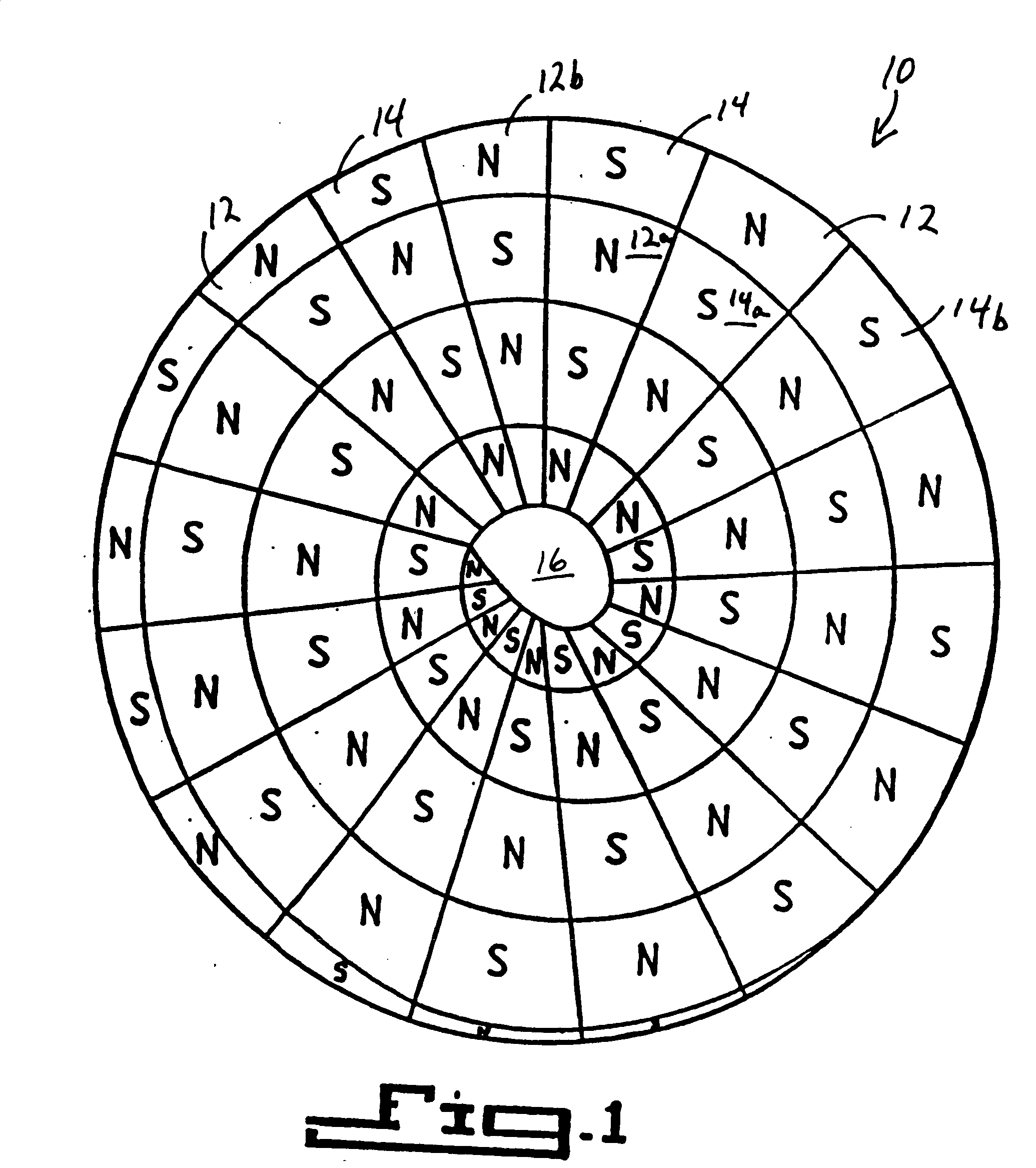
[0020] To overcome the limitation of the previous patents described above, the present invention provides a new configuration which does in fact affect blood vessels in any orientation in the body under which the device is placed. This present invention includes a pattern of constantly alternating polarity zones, preferably in a spiral configuration, arranged in such a way as to produce magnetic fields which alternate radially as well as circumferentially. It can be clearly shown that no matter how blood vessels are situated under the present invention, then they must cross through alternating magnetic fields and therefore receive an optimal effect. Even though a blood vessel might cross near the periphery of the device, it still passes through several alternating magnetic fields and therefore experiences an optimal effect. Furthermore, the average distance between poles remains relatively constant, whereas with the Baermann '532 device the distance which blood must travel before passing through alternating magnetic fields varies dramatically for those blood vessels not situated across the center of the device, thus minimizing its effectiveness.
[0032] Therefore, it is an object of the present invention to provide a therapeutic magnetic pad of constantly alternating polarity zones which is effective no matter where a blood vessel traverses the pad.

Problems solved by technology

However, with respect to the concentric ring configuration of Baermann '532, the effective orientation for the concentric ring design is limited because of the assumption that all blood vessels will cross through the center of the device.
The Baermann '532 device becomes progressively less effective as blood vessels are positioned away from the center until the device is non-effective at its peripheral outer ring, where a blood vessel will only transverse one pole with no increase in blood flow.
However, the Baermann '532 “body site” is limited to an area where blood vessels traverse across the center of the device and therefore the therapeutic effects of the magnetic pad on the blood vessels covered by the area of the pad is diminished because of the necessity for all blood vessels to traverse the center.
In reality, however, this ideal arrangement of blood vessels cannot be expected.
However, this alternate embodiment of the Baermann '532 device is only effective near the peripheral areas of the device, since a blood vessel traversing at or near the center of the pad will substantially pass only through one polarity, crossing the pad from “north to north” or “south to south” only.
Therefore, the Baermann '532 device cannot overcome the limitations of the concentric ring design by adding more rings in a more densely packed arrangement since decreasing the width of the rings to less than 4 mm would be of no therapeutic value.
Therefore, the Baermann '532 device is limited in the number of rings used in the device since the width of the rings must decrease as the number of rings increases.
(Kitagishi), limitations exist as to the alternation of magnetic polarity that is seen as provided a degree of magnetotherapeutic ability as the Kitagishi device enjoys only a limited degree of magnetic polarity alternation.

Method used


Image

  • Flexible magnetic pad with multi-directional constantly alternating polarity zones
  • Flexible magnetic pad with multi-directional constantly alternating polarity zones
  • Flexible magnetic pad with multi-directional constantly alternating polarity zones

Examples


Embodiment Construction

)

[0044] The detailed description set forth below in connection with the appended drawings is intended as a description of presently-preferred embodiments of the invention and is not intended to represent the only forms in which the present invention may be constructed and / or utilized. The description sets forth the functions and the sequence of steps for constructing and operating the invention in connection with the illustrated embodiments. However, it is to be understood that the same or equivalent functions and sequences may be accomplished by different embodiments that are also intended to be encompassed within the spirit and scope of the invention.

[0045] Referring to the drawings where like numerals of reference designate like elements throughout it will be noted that as shown in FIG. 1, there is provided a flexible magnetic pad 10 having alternating north and south polarity zones denoted by reference numerals 12 and 14. The alternating polarity zones 12 and 14 are arranged in...


PUM


Abstract

A flexible magnetic pad is provided with constantly alternating polarity zones which therapeutically affect blood vessels to increase blood flow, irrespective of the orientation of any blood vessel with respect to the pad, the polarity zones being arranged in an alternating pattern throughout the pad.

Description

CROSS-REFERENCES TO RELATED APPLICATIONS [0001] This patent application is a continuation-in-part of U.S. patent application Ser. No. 09 / 855,815 filed May 14, 2001 which is a continuation-in-part to U.S. patent application Ser. No. 09 / 212,737 filed Dec. 15, 1998, now U.S. Pat. No. 6,328,684, which is a continuation of application Ser. No. 08 / 678,348 filed Jul. 11, 1996, now U.S. Pat. No. 5,871,438, which is a continuation-in-part of application Ser. No. 08 / 573,390 filed Dec. 15, 1995, now U.S. Pat. No. 5,538,495, which is a continuation of application Ser. No. 08 / 427,733 filed Apr. 24, 1995, now U.S. Pat. No. 5,514,072, which is a continuation of application Ser. No. 08 / 276,876 filed Jul. 18, 1994, now abandoned, which is a continuation of application Ser. No. 08 / 158,607 filed Nov. 29, 1993, now abandoned, which is a continuation of application Ser. No. 07 / 990,927 filed Dec. 14, 1992, now U.S. Pat. No. 5,277,692, which is a continuation of application Ser. No. 07 / 823,149 filed Jan. ...

Claims


Application Information

Patent Timeline
IPC IPC(8): A61N2/06A61N2/08
CPCA61N2/06
Inventor ARDIZZONE, VINCENT
Owner NYUU MAGUNETEIKUSU
Learn More