
Apparatus for fail-safely disconnecting an electrical load; in particular in industrial production plants

a technology for electrical load and apparatus, applied in emergency protective arrangements for automatic disconnection, relays, instruments, etc., can solve the problems of inconvenient method and no longer useful connection, and achieve the effect of quick installation in production systems and simple and fast manners

Inactive Publication Date: 2005-03-17
PILZ (COMPANY)
View PDF7 Cites 46 Cited by
  • Summary
  • Abstract
  • Description
  • Claims
  • Application Information

AI Technical Summary

Benefits of technology

The present invention provides an apparatus for safely switching electrical loads that can be installed and connected in a simpler and faster manner, and at lower cost. The apparatus includes two safety switching devices that are connected via a single-channel connecting line, which simplifies the installation process. The first safety switching device has an evaluation and control unit, an output, and an electronic switching element for producing a potential-related switching signal. The second safety switching device has at least two input stages that receive the potential-related switching signal redundantly with each other, allowing for failsafe monitoring and disconnection of the electrical load. The invention also provides a method for evaluating the potential-related switching signal and a refinement for transmitting mutually redundant information to the second safety switching device.

Problems solved by technology

Owing to the potential-related outputs, it is no longer useful to connect the outputs of two or more safety switching devices according to WO 01 / 67610 A1 in series with one another in order to implement an apparatus comprising a plurality of safety switching devices.
However, this method is not suitable for a combination of two or more safety switching devices of the type described above to form a system of safety switching devices as is known from WO 01 / 67610 A1 .

Method used


Image

  • Apparatus for fail-safely disconnecting an electrical load; in particular in industrial production plants
  • Apparatus for fail-safely disconnecting an electrical load; in particular in industrial production plants
  • Apparatus for fail-safely disconnecting an electrical load; in particular in industrial production plants

Examples


Embodiment Construction

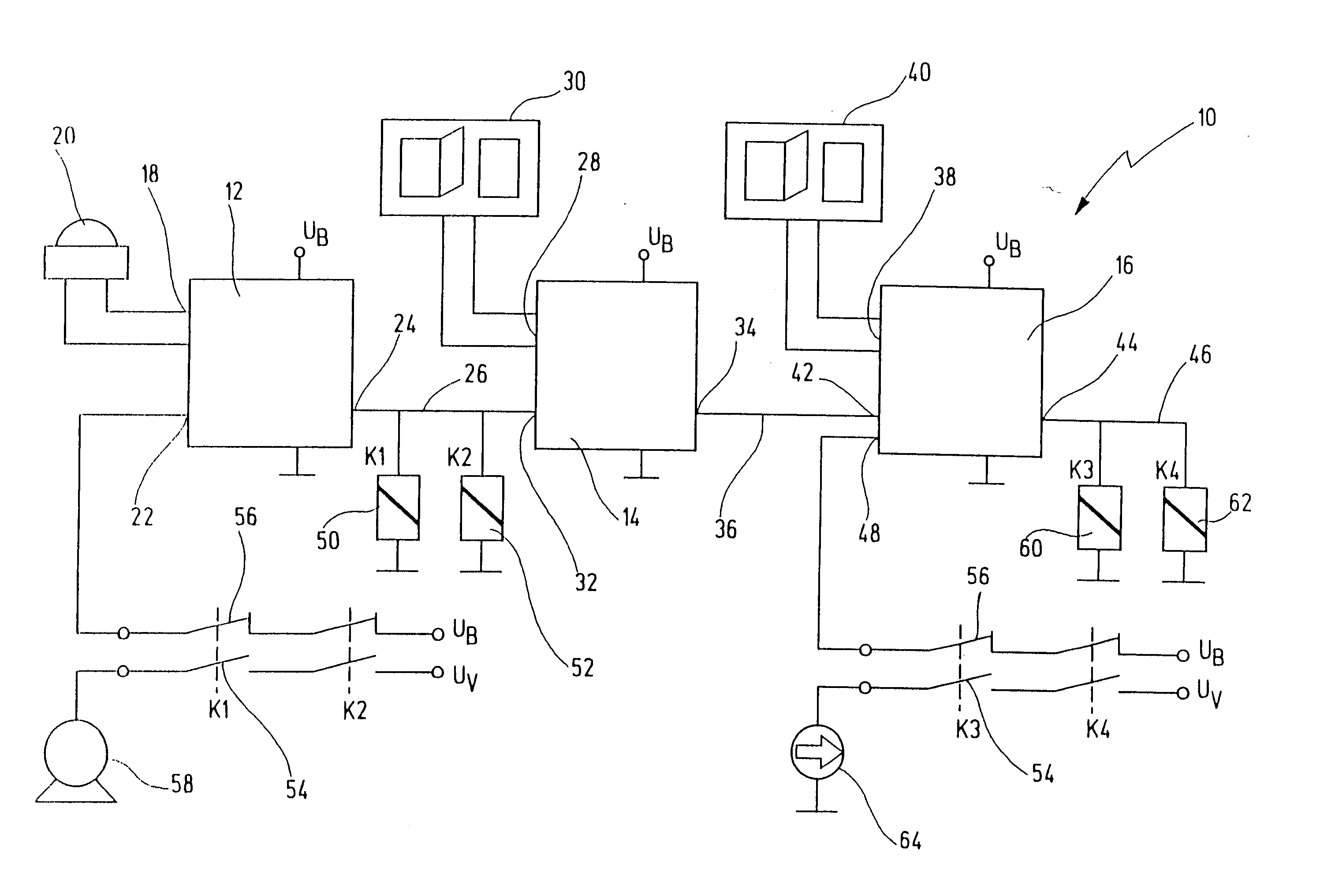
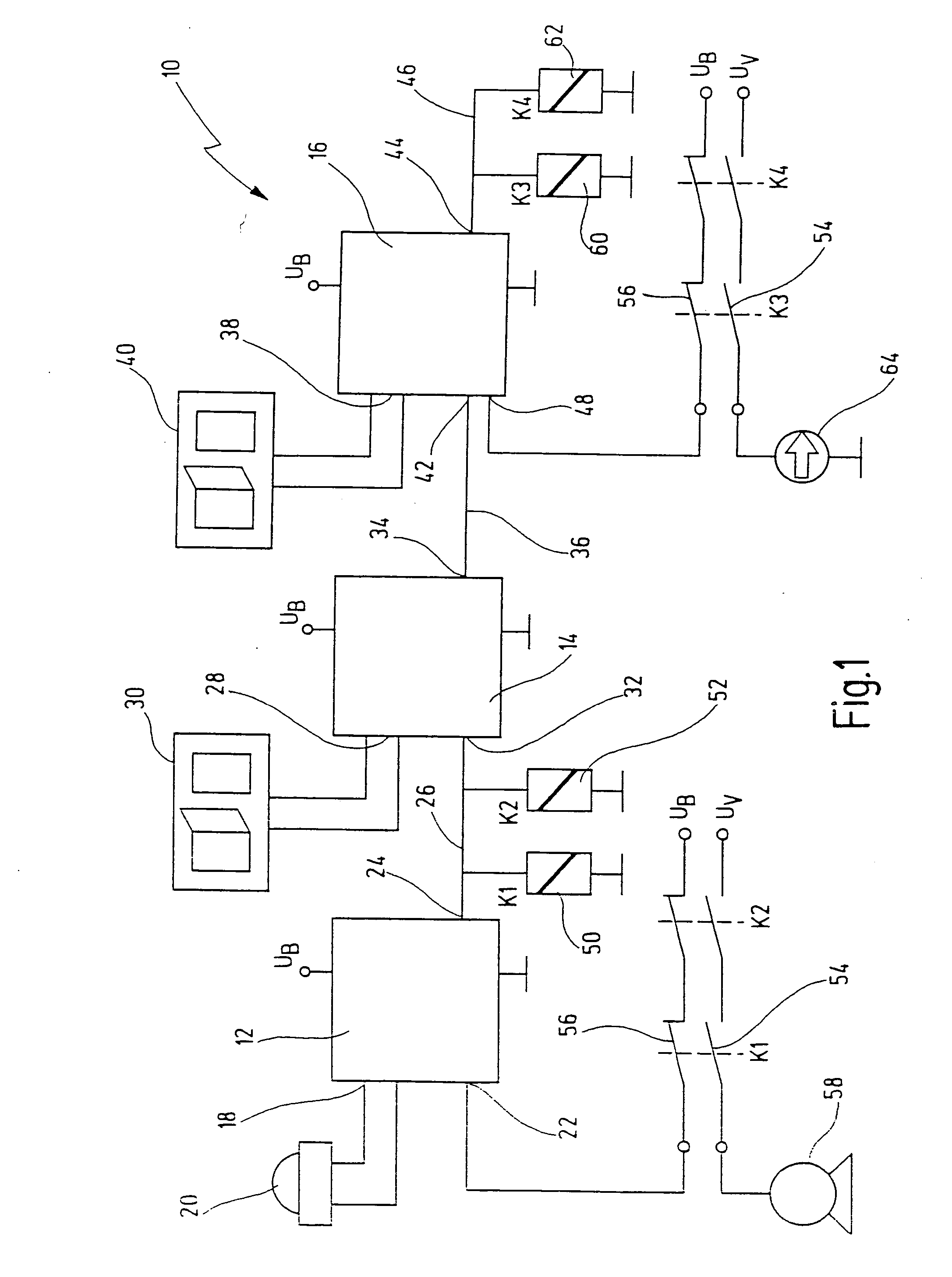
[0041] In FIG. 1, reference number 10 denotes an apparatus according to the invention in its totality.

[0042] In the present embodiment, the apparatus 10 comprises three safety switching devices 12, 14, 16, which are combined to form a safety switching device system, in the manner which will be explained in the following text. The safety switching device 12 is a first safety switching device based on the terminology of the present invention, and it has an input 18 to which, in this case, an emergency stop button 20 is connected via two channels. A further input is annotated with the reference number 22. A feedback signal is connected to this input in a manner which will be described in more detail in the following text.

[0043] The safety switching device 12 furthermore has a single-channel output 24, to which a single-channel connecting line 26 is connected.

[0044] In principle, the safety switching device 14 is physically similar to the safety switching device 12. However, it diffe...


PUM


Abstract

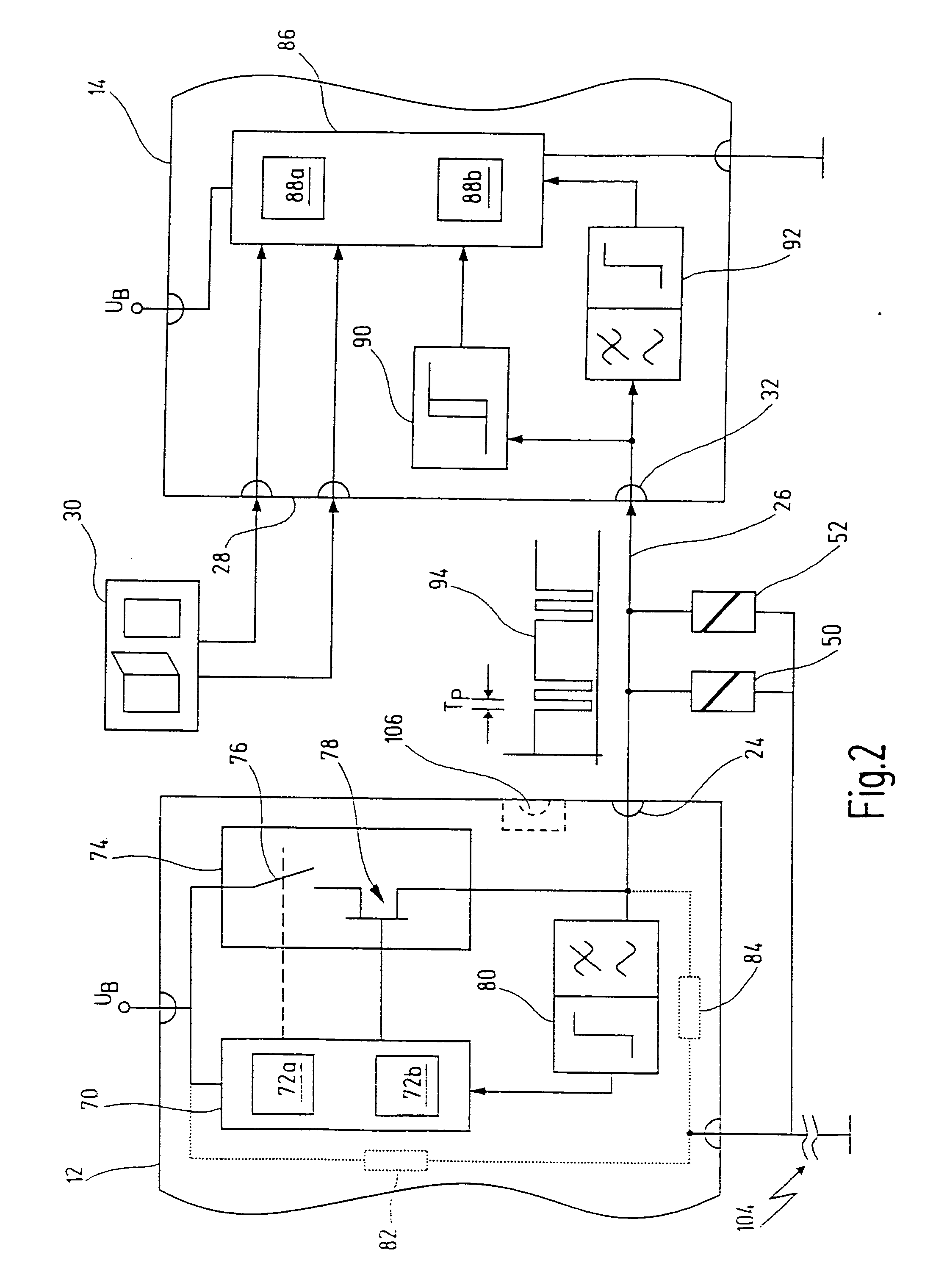
An apparatus for failsafe disconnection of an electrical load has a first and at least one second safety switching device. The first safety switching device has a first evaluation and control unit, an output and an electronic switching element, for producing a potential-related switching signal at the output under the control of the first evaluation and control unit. The second safety switching device has a second evaluation and control unit and an input. The input and the output are connected to one another via a single-channel connecting line, and the input supplies the second evaluation and control unit with the potential-related switching signal from the output of the first safety switching device. In order to fulfill safety standards for such kind of apparatus, the second safety switching device has at least two input circuits to which the potential-related switching signal from the output of the first safety switching device is supplied in a mutually redundant manner.

Description

RELATED APPLICATIONS [0001] The present application is a continuation of international patent application PCT / EP03 / 02903 filed Mar. 20, 2003 and published as WO 03 / 085313 in German language, which claims a priority under the Paris convention from German patent application DE 102 16 226.3 filed on Apr. 8, 2002.BACKGROUND OF THE INVENTION [0002] The present invention generally relates to an apparatus for fail-safely disconnecting an electrical load, and more particularly to an apparatus having a first and at least one second safety switching device. The invention also relates to safety switching devices for use in such an apparatus. [0003] Safety switching devices are particularly used in industrial production environments in order to reliably and safely disconnect machines, such as a hydraulic press or a milling machine, when this is necessary for the safety of operators, or for other reasons. Safety switching devices of this generic type typically have one or more input terminals, t...

Claims


Application Information

Patent Timeline
Patent Type & Authority Applications(United States)
IPC IPC(8): G05B9/03F16P3/00H01H47/00
CPCH01H47/004G05B9/03
Inventor PULLMANN, JURGENEHRLICH, GERHARD
Owner PILZ (COMPANY)
Learn More