Combustor drain valve
- Summary
- Abstract
- Description
- Claims
- Application Information
AI Technical Summary
Benefits of technology
Problems solved by technology
Method used
Image
Examples
Embodiment Construction
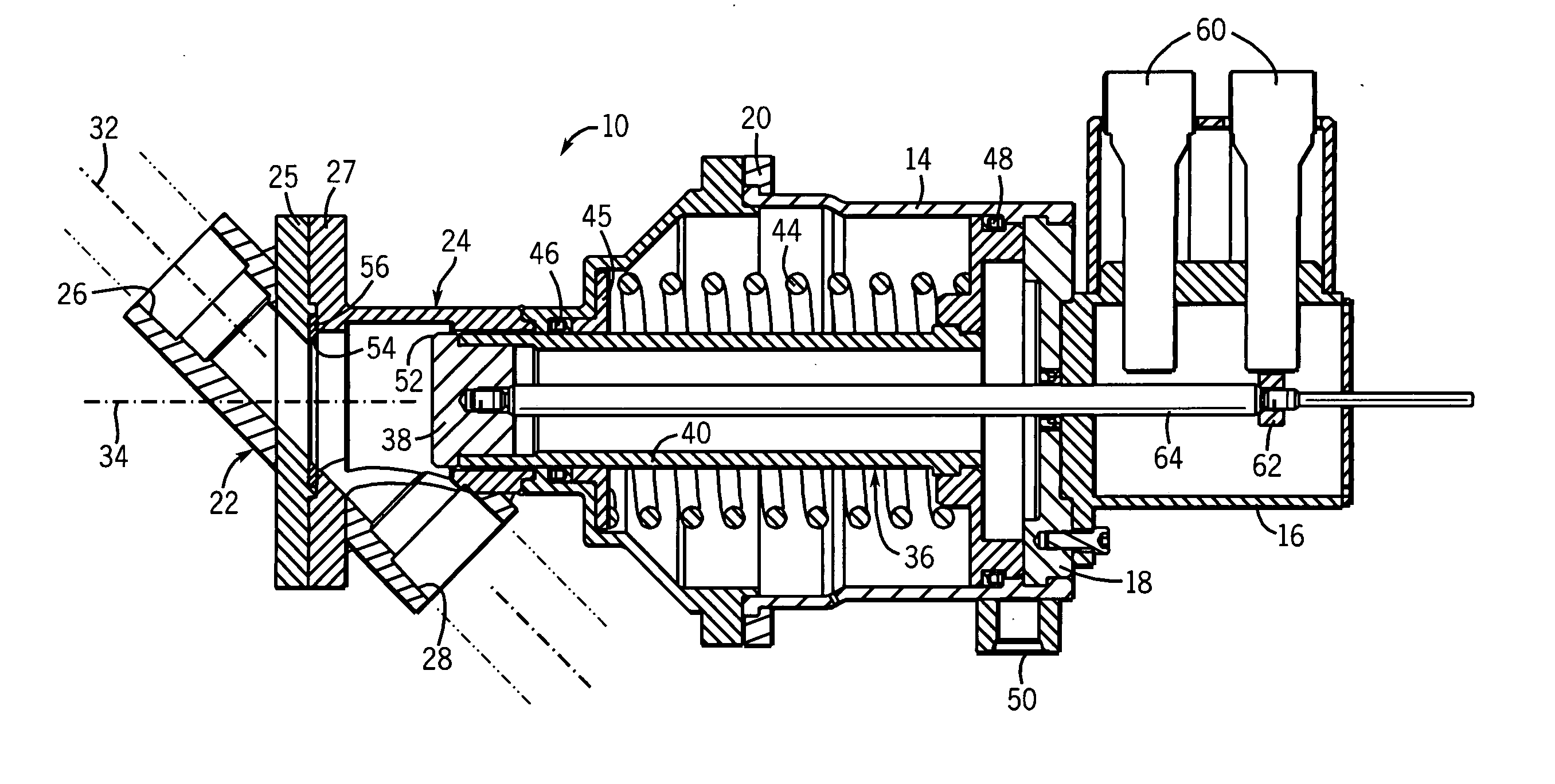
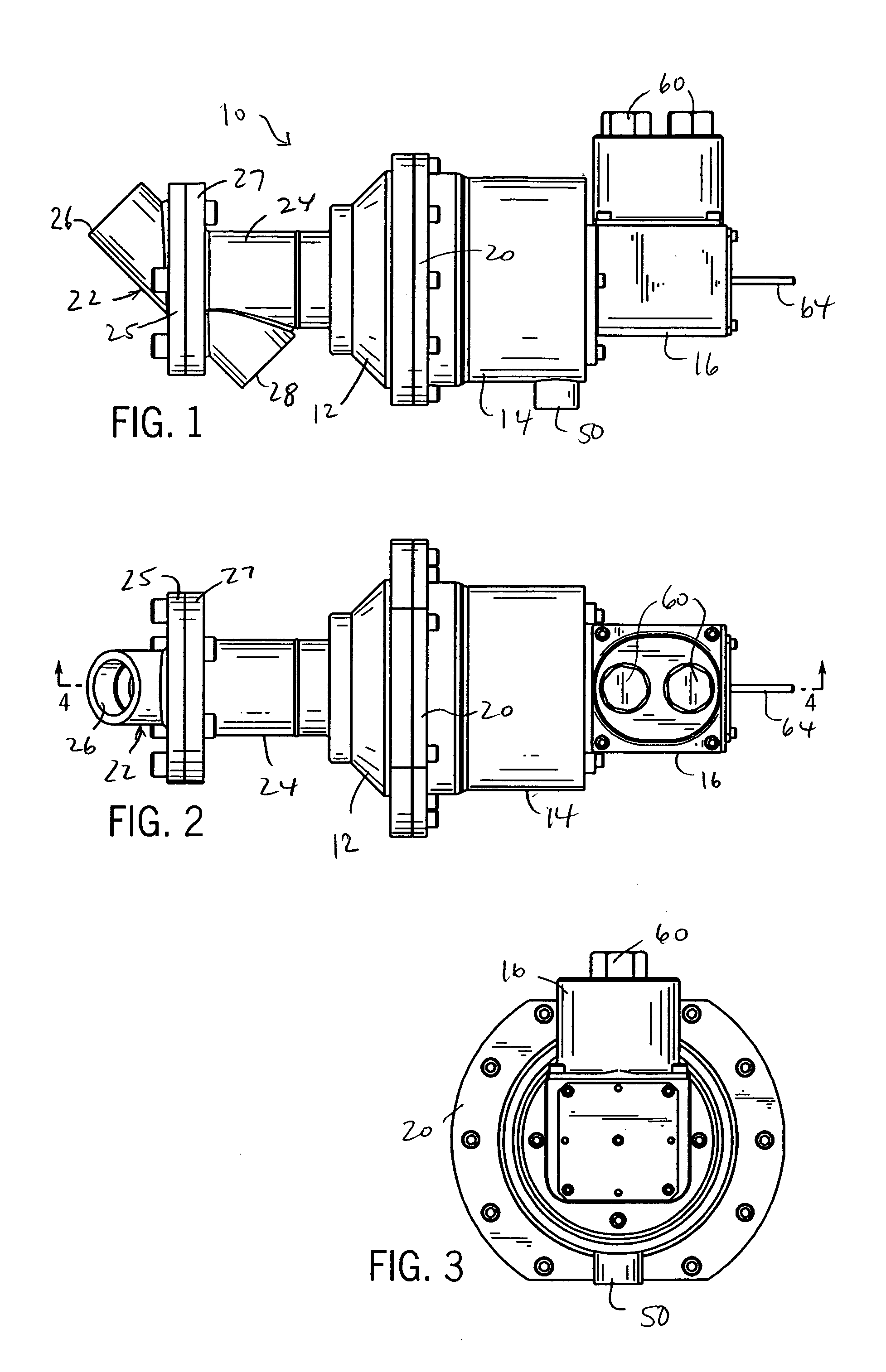
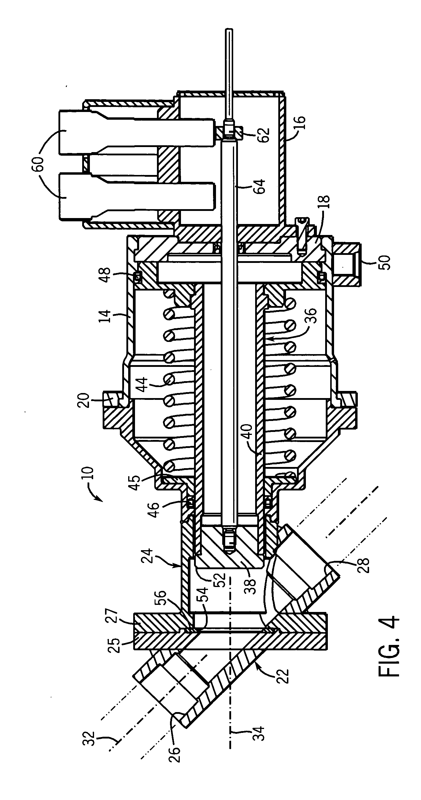
[0025] Referring to FIGS. 1-3 of the drawings, a combustor drain valve 10 of the present invention includes a body with a main housing 12, an actuator housing 14 and a position feedback housing 16. The body can be constructed of one or more separate sections joined together as needed. In the preferred form shown, the actuator housing 14 has an end cap 18 (see FIG. 4) welded to an end to which the position feedback housing 16 bolts. A retainer ring 20 is bolted in place to secure the other end of the actuator housing 14 to the main housing 12.
[0026] As shown in FIGS. 1 and 4, the main housing 12 is in part formed of two sections 22 and 24 bolted together at respective flanges 25 and 27. These two sections 22 and 24 define respective inlet 26 and outlet 28 sections of a drain passageway 30. The inlet 26 and outlet 28 have open ends that are designed to accept fittings or other couplers for joining the valve to lines leading from the combustion can(s) of a turbine engine and a drain c...
PUM
 Abstract
Description
Claims
Application Information
 - R&D
- Intellectual Property
- Life Sciences
- Materials
- Tech Scout
- Unparalleled Data Quality
- Higher Quality Content
- 60% Fewer Hallucinations
Browse by: Latest US Patents, China's latest patents, Technical Efficacy Thesaurus, Application Domain, Technology Topic, Popular Technical Reports.
© 2025 PatSnap. All rights reserved.Legal|Privacy policy|Modern Slavery Act Transparency Statement|Sitemap|About US| Contact US: help@patsnap.com


