
Coated substrate and process of preparation thereof

a technology of coating substrate and coating process, applied in the field of coating substrate, can solve the problems of inability to successfully coat, ceramic and metallic substrates having high cell densities of more than 600 cells per square inch, and inability to achieve such substantially uniform coatings

Inactive Publication Date: 2005-03-10
ENGELHARD CORP
View PDF59 Cites 27 Cited by
  • Summary
  • Abstract
  • Description
  • Claims
  • Application Information

AI Technical Summary

Benefits of technology

"The invention is about a coated substrate that contains a layer of coating that can be a non-sorbent, non-catalytic material, a sorbent, non-catalytic material, a catalytic material, or a mixture of two or more of these materials. The substrate can also have openings, corrugations, or tabs located at or in the walls of cells. The invention also includes monoliths that have odd shapes, non-symmetrical monoliths, or monoliths with cell densities in excess of 700 cells per square inch. The patent also describes a process for preparing these coated substrates and monoliths."

Problems solved by technology

However, the prior art substrates, particularly those that comprise metal foils containing a multiplicity of openings have not been successfully coated to date so as to create substantially uniform layers of desired non-sorbent, sorbent and / or catalytic coatings on the surfaces of such foils.
Further, both ceramic and metallic substrates having high cell densities of greater than 600 cells per square inch have not been successfully coated to date with such substantially uniform layers.

Method used


Image

  • Coated substrate and process of preparation thereof
  • Coated substrate and process of preparation thereof
  • Coated substrate and process of preparation thereof

Examples


Embodiment Construction

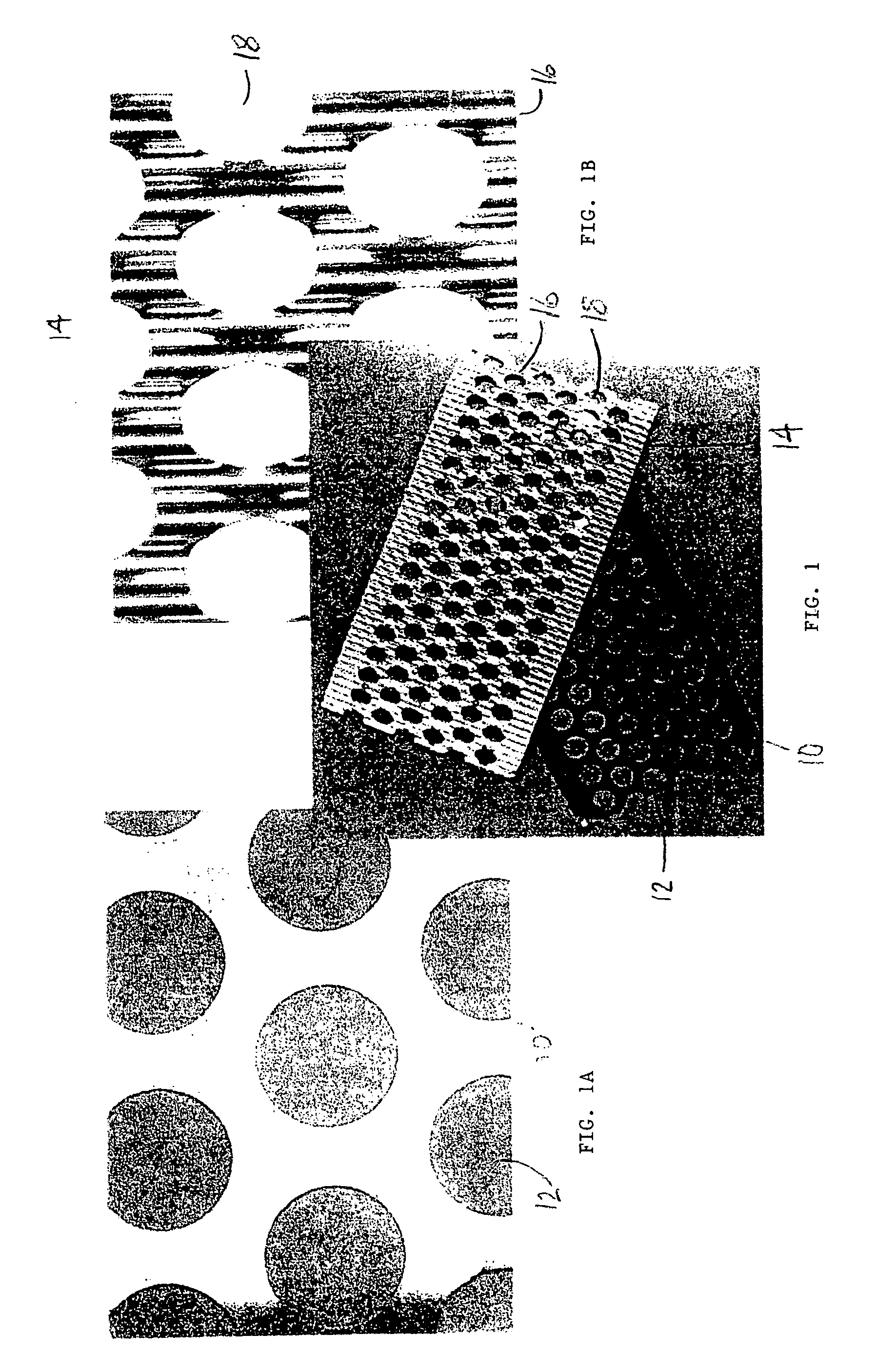
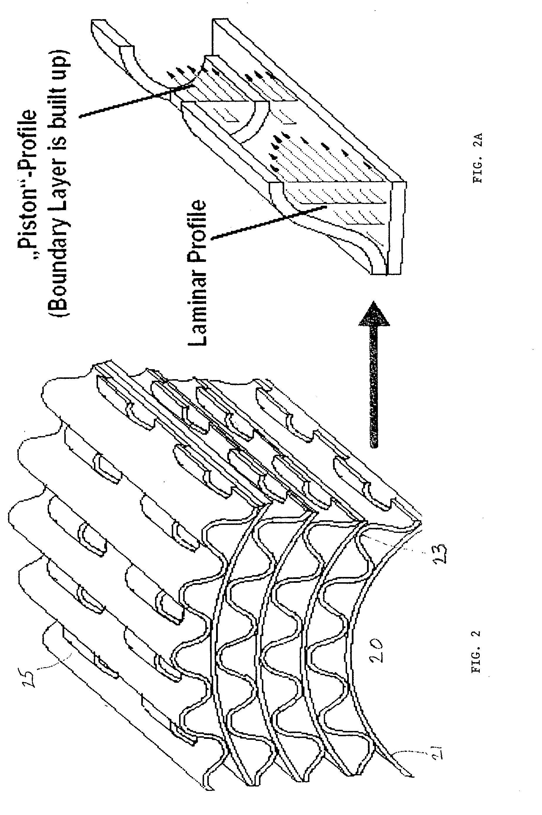
[0037] The substrate, frequently referred to in the prior art as a monolithic carrier, comprises a plurality of inlets; a plurality of outlets; a plurality of substrate walls; and a plurality of channels defined by the substrate walls, said channels extending directly or indirectly from at least one outlet; and wherein there are a plurality of openings in the substrate walls that communicate between adjacent channels. Typically, the channels are defined by walls on which the coating material is uniformly deposited so that exhaust gases flowing through the channels will contact the coating material. Typically, the channel walls are continuous without perforations or extensions from the wall surfaces, such as tabs. The channels can be of any suitable cross-sectional shape and size such as trapezoidal, rectangular, square, sinusoidal, hexagonal, oval, circular, etc. The substrate preferably comprises a honeycomb body.

[0038] In a first embodiment of the invention, the substrate compris...


PUM

PropertyMeasurementUnit
thicknessaaaaaaaaaa
thicknessaaaaaaaaaa
thicknessaaaaaaaaaa

Abstract

A substantially uniformly coated substrate that may be either metallic or ceramic in nature as well as a process for preparing such coated substrate. The substantially uniformly coated substrate typically comprises a plurality of outlets; a plurality of substrate walls; and a plurality of channels defined by the substrate walls, said channels extending directly or indirectly from at least one outlet; and wherein there are a plurality of openings and / or corrugations and / or tabs in the substrate walls that communicate between adjacent channels, said substrate containing at least one substantially uniform layer of a coating material that may be a non-sorbent, non-catalytic material; a sorbent, non-catalytic material; a catalytic material or a mixture of two or more of the foregoing materials. The process for preparing such coated substrate involves immersing the substrate in a slurry of the desired material or materials, centrifuging the substrate so as to thereby distribute the material or materials as a substantially uniform layer on the substrate and remove any material or materials in excess of that desired to be present on the substrate, and thereafter drying and calcining the coated substrate.

Description

CROSS-REFERENCE TO RELATED APPLICATION [0001] This application claims the benefit of U.S. Provisional Application No. 60 / 501,136 filed Sep. 8, 2003, the entire contents of which are herein incorporated by reference.FIELD OF THE INVENTION [0002] The invention pertains to a substrate having a substantially uniform layer of coating thereon and to a process for preparing such coated substrate. The coated substrate is useful for treating the exhaust gas stream emitted from an automotive engine, i.e., a gasoline or diesel internal combustion engine, to thereby reduce the level of unburned hydrocarbons, carbon monoxide and nitrogen oxides that may be present in such gas stream. BACKGROUND OF THE INVENTION [0003] Substrates useful for the present invention are known in the prior art. Coated metal foils are also know in the prior art, e.g., see U.S. Pat. No. 5,958,829. However, the prior art substrates, particularly those that comprise metal foils containing a multiplicity of openings have n...

Claims


Application Information

Patent Timeline
Patent Type & Authority Applications(United States)
IPC IPC(8): B01D53/94B01J35/00B01J35/04B01J37/02C23C2/04C23C2/14C23C2/26C23C26/02C23C30/00F01N3/28
CPCB01D53/9454B01J35/0006B01J35/04B01J37/0225C23C2/04Y02T10/22C23C2/26C23C26/02C23C30/00F01N3/281C23C2/14B01J35/19B01J35/56Y02T10/12
Inventor STEINKE, MICHAELFAHRENSOHN, KLAUSKRAUM, MARTINNEUBAUER, TORSTEN
Owner ENGELHARD CORP
Learn More