Image scanner provided with power saving mode and a system having a power saving mode
- Summary
- Abstract
- Description
- Claims
- Application Information
AI Technical Summary
Benefits of technology
Problems solved by technology
Method used
Image
Examples
first transformed example
(a) FIRST TRANSFORMED EXAMPLE
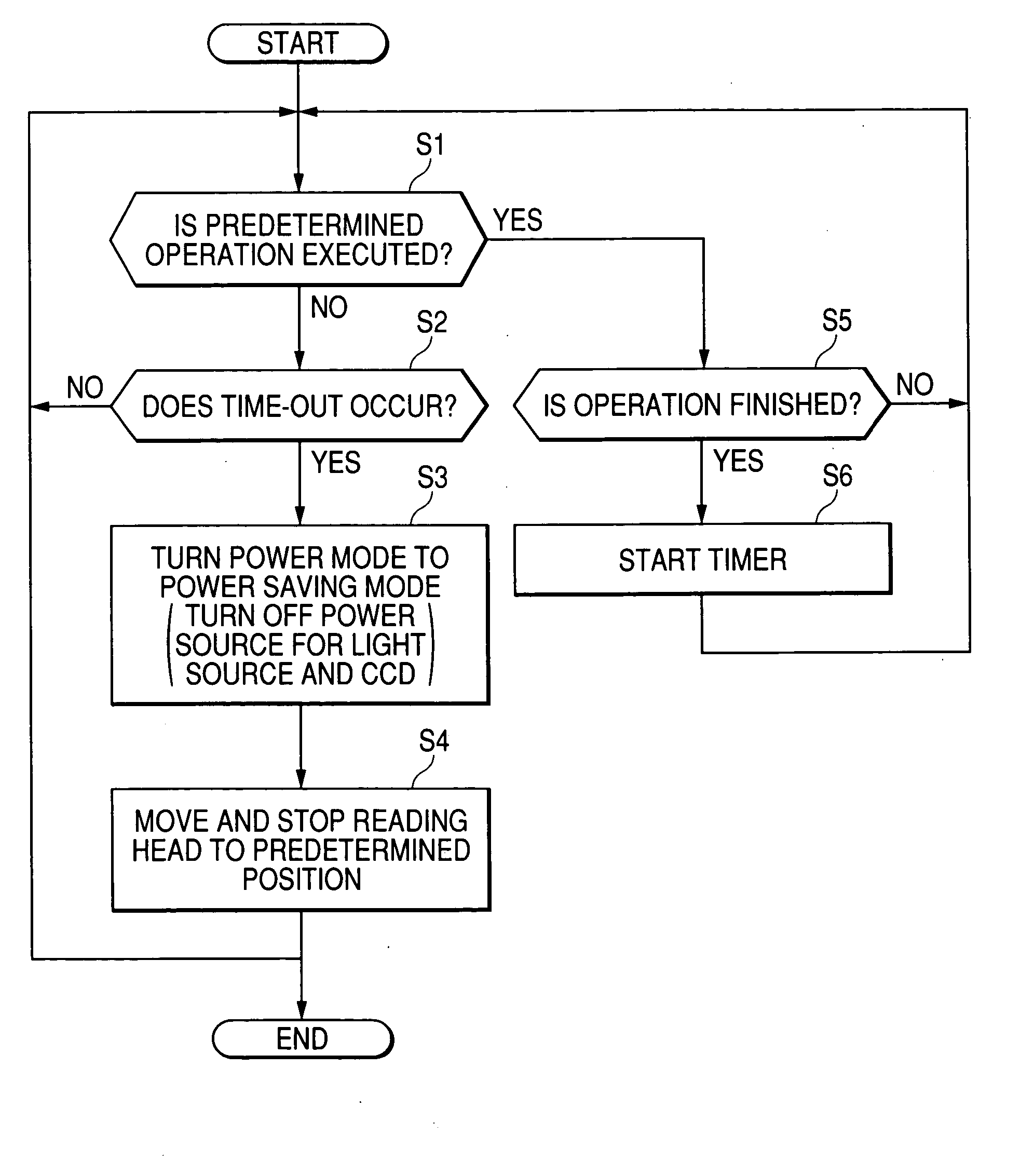
[0148] The power saving mode includes a sub power saving mode and a main power saving mode. In case the normal power mode is turned to the power saving mode, transition is made in the order of the sub power saving mode from the normal power mode and the main power saving mode from the sub power saving mode. In case the power saving mode is turned to the normal power mode, the power saving mode is released in the order of the sub power saving mode from the main power saving mode and the normal power mode from the sub power saving mode. Concretely, the controller 45 stops the supply of power to light-sensitive unit for reading (in the above embodiment, the linear CCD 27) or reduces supplied power to the light-sensitive unit for reading than that in the normal power mode when the normal power mode is turned to the sub power saving mode. When fixed time elapses since that time, the controller 45 turns the sub power saving mode to the main power saving mode, ...
second transformed example
(b) SECOND TRANSFORMED EXAMPLE
[0149] The predetermined detective threshold EX may be also a fixed value and may be also a variable value. In the case of the latter, the controller 45 varies by the following method.
[0150] That is, another optical sensor which can sense a beam irradiating the outside surface of the scanner 1 is arranged on the outside surface of the image scanner 1 (hereinafter, another optical sensor is called a peripheral optical sensor) and light sensed by the optical sensor is called peripheral light). The peripheral optical sensor inputs a signal having a value according to the intensity of sensed peripheral light to the controller 45.
[0151] A threshold table in which plural detective thresholds corresponding to plural peripheral light intensity are recorded is prepared in the memory (for example, EEPROM) in the image scanner 1.
[0152] The controller 45 acquires the detective threshold EX corresponding to a value of a signal input from the peripheral optical se...
third transformed example
(c) THIRD TRANSFORMED EXAMPLE
[0154] In case power is also supplied to the read image output device 43 from a predetermined power circuit and the read image output device 43 also has a power saving mode and a normal power mode, the controller 45 turns the power mode of the read image output device 43 to the normal power mode or to the power saving mode based upon a signal value from the external light sensor 100. Concretely, the controller 45 turns the read image output device 43 to the power saving mode (concretely, stops the supply of power to the read image output device 43 or reduces supplied power to it) in case the supply of power to at least one of the light-sensitive unit for reading and the light source is stopped or supplied power to at least one is reduced when the read image output device 43 is in the normal power mode. Besides, the controller 45 releases the power saving mode of the read image output device 43 (concretely, starts the supply of power to the read image out...
PUM
 Abstract
Description
Claims
Application Information
 - R&D
- Intellectual Property
- Life Sciences
- Materials
- Tech Scout
- Unparalleled Data Quality
- Higher Quality Content
- 60% Fewer Hallucinations
Browse by: Latest US Patents, China's latest patents, Technical Efficacy Thesaurus, Application Domain, Technology Topic, Popular Technical Reports.
© 2025 PatSnap. All rights reserved.Legal|Privacy policy|Modern Slavery Act Transparency Statement|Sitemap|About US| Contact US: help@patsnap.com


