Micro-adjustment device for the angle stop plank of a planer

a planer and angle stop technology, which is applied in the direction of metal-working machine components, flat surfacing machines, manufacturing tools, etc., can solve the problems of inability to fully meet the needs of planing work and inability to plane wood material with great accuracy, and achieve the effect of accurate micro-adjustmen

Active Publication Date: 2005-03-10
JPW IND
View PDF7 Cites 5 Cited by
  • Summary
  • Abstract
  • Description
  • Claims
  • Application Information

AI Technical Summary

Benefits of technology

[0006] A main objective of the invention is to offer a micro-adjustment device for the angle stop plank of a planer, able to accurately micro-adjust the stop plank of a planer at any angle from an interior angle of 45 degrees to an exterior angle of 45 degrees by turning around a hand wheel.
[0007] Another objective of the

Problems solved by technology

To carry out planing at a specific angle, it is necessary to draw a line on wood material in advance and then perform planing with help of certain auxiliary tools, impossible to plane the wood material with great accuracy, inconvenient in planing wok and likely to cause danger during planing.
However

Method used


Image

  • Micro-adjustment device for the angle stop plank of a planer
  • Micro-adjustment device for the angle stop plank of a planer
  • Micro-adjustment device for the angle stop plank of a planer

Examples


Embodiment Construction

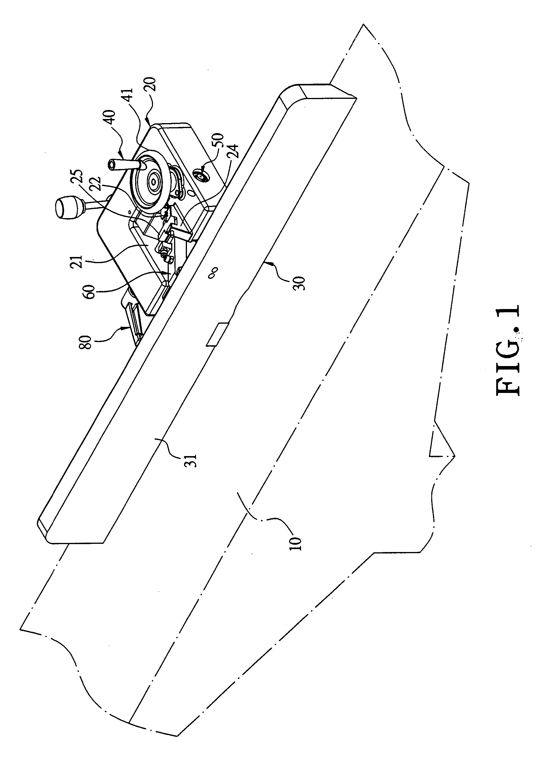
[0017] A preferred embodiment of a micro-adjustment device for the angle stop plank of a planer in the present invention, as shown in FIGS. 1 to 4, includes a wood-conveying table 10, a holding frame 20, a stop plank 30, a hand wheel unit 40, a transmission rod 50, an upper connecting rod 60, a lower connecting rod 70 and a locking handle 80 combined together.

[0018] The wood-conveying table 10 has one side combined with the upper holding frame 20 connected with the stop plank 30, which is located at one side on the topside of the wood-conveying table 10 for a wood material to be leaned thereon during planing.

[0019] The holding frame 20 is an inverted-U shaped body, having an accommodating space 21 formed in the center, and an index hand 22 provided at a preset location of the topside and pointing to one side of the accommodating space 21.

[0020] The stop plank 30 has its front side formed with a leaning surface 31 for a wood material to lean thereon and its rear lower side locked ...


PUM


Abstract

A micro-adjusting device for the angle stop plank of a planer includes a hand wheel unit provided on the holding frame and having a worm, a transmission rod provided in the holding frame to be rotated by the worm, an upper connecting rod meshed with and actuated to move back and forth by a transmission gear fixed on one end of the transmission rod and having one end pivotally connected with a stop plank, and a lower connecting rod having its opposite ends respectively connected pivotally with the stop plank and the holding frame to form two pivotal joints serving as turning fulcrums. When the hand wheel unit is turned around, the upper connecting rod is actuated to pull or push the upper portion of the stop plank, and the lower connecting rod together with the turning fulcrums micro-adjusts the stop plank at a required angle.

Description

BACKGROUND OF THE INVENTION [0001] 1. Field of the Invention [0002] This invention relates to a micro-adjustment device for the angle stop plane of a planer, particularly to one able to micro-adjust the slanting angles of the angle stop plank of a planer accurately and quickly. [0003] 2. Description of the Prior Art [0004] A conventional planer has a stop plank positioned stationary on its wood conveying table, always maintaining a single angle between the stop plank and the wood conveying table; therefore after a wood material is positioned to lean on the stop plank for planing, it can be planed only at a single angle, impossible to be planed at a specific angle. To carry out planing at a specific angle, it is necessary to draw a line on wood material in advance and then perform planing with help of certain auxiliary tools, impossible to plane the wood material with great accuracy, inconvenient in planing wok and likely to cause danger during planing. In view of the above-mentioned...

Claims


Application Information

Patent Timeline
IPC IPC(8): B27C1/02B27C1/12
CPCB27C1/12B27C1/02
Inventor CHUANG, BOR YANN
Owner JPW IND
Why Eureka
Try Eureka