
Snorkel with light-emitting device

a light-emitting device and snorkel technology, applied in underwater equipment, lighting and heating apparatus, light-support devices, etc., can solve the problems of difficulty even arising, accidents often occur, and the effectiveness of light-reflecting warnings cannot be implemented, so as to facilitate the finding of fellow companions, the effect of safeguarding the safety of the diver

Inactive Publication Date: 2005-03-03
KUO TZONG FUH
View PDF5 Cites 14 Cited by
  • Summary
  • Abstract
  • Description
  • Claims
  • Application Information

AI Technical Summary

Benefits of technology

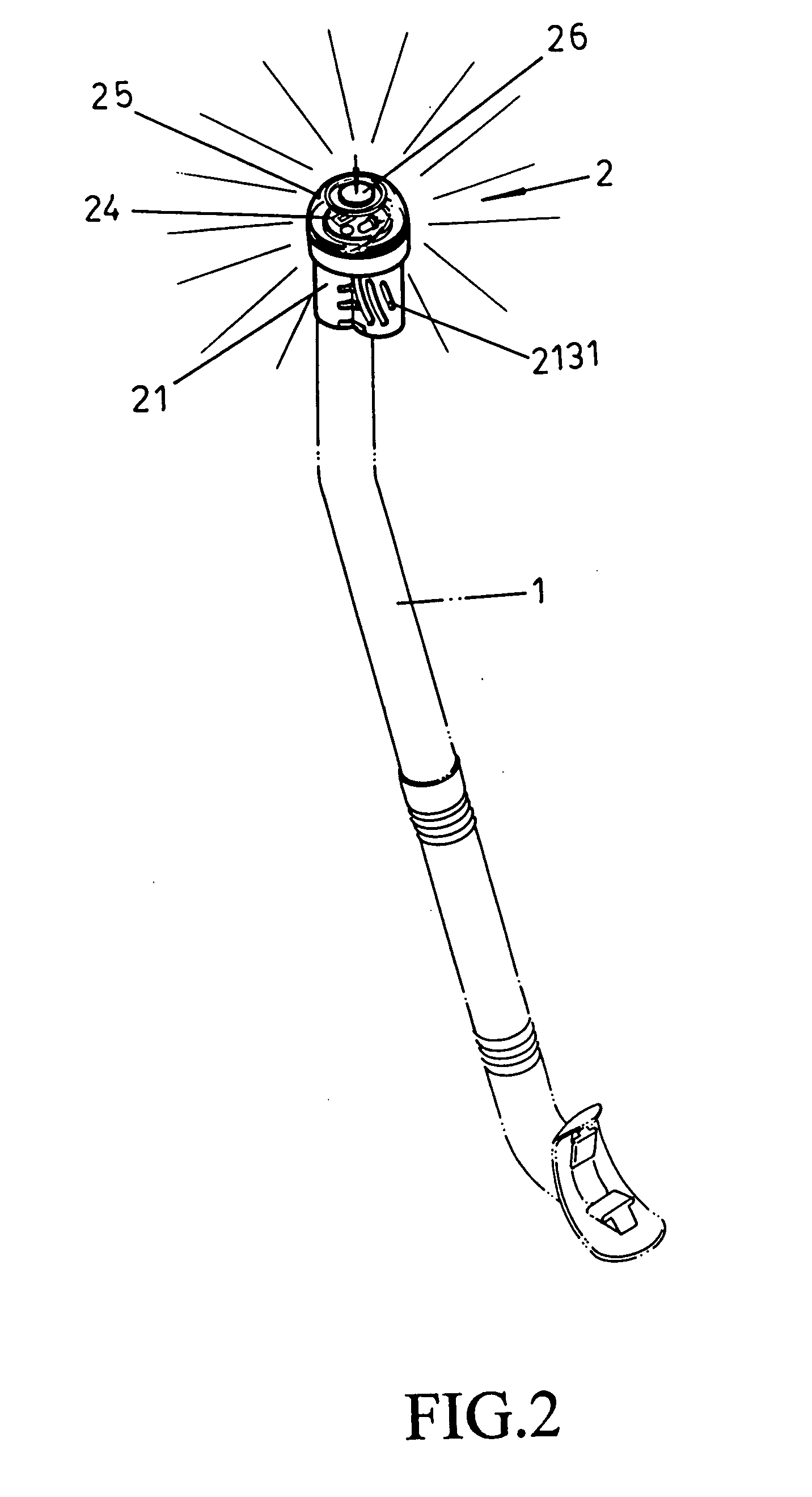
[0006] The primary objective of the present invention is to provide a light-emitting device attached to a topmost portion of snorkel. The light-emitting device comprises batteries to supply electricity to LEDs. Upon pressing down on a button configured on the head of the light-emitting device, a switch on a circuit board is actuated, thereupon light is emitted through the transparent light-emitting device thereof. The light-emitting device is applicable for usage by divers on cloudy days or when diving at night, whereby a safety warning effectiveness is maintained, thus preventing being hit by sailing vessels or speeding motorboats, and safeguarding the safety of the diver thereof. Moreover, the light-emitting device facilitates fellow companions finding a diver should the diver lose their direction.

Problems solved by technology

However, the light-reflecting tape 200 still possesses shortcomings, for example, when being used on cloudy days or at night time when sunlight is lacking, making it impossible to implement the effectiveness of the light-reflecting warning, resulting in accidents often occur whereby the diver is hit by a sailing vessel or speeding motorboat.
Difficulties even arise because the diver has lost direction and unable to locate their companions.
Referring to prior art U.S. Pat. Nos. 5,622,422, 5,553,606, and 5,701,884, the light-emitting devices are all for usage under the water surface, resulting in the brightness of the emitting light being insufficient for anyone above the surface to notice, and only able to provide sufficient light for companions in the vicinity to see.
Moreover, the structure of the aforementioned patents are very simple, only taking into consideration the light-emitting feature of the light bulb or LED, and not enhancing the water proofing effectiveness of the unit itself, thus resulting in the light-emitting device easily faltering or failing upon immersing in the water.

Method used


Image

  • Snorkel with light-emitting device
  • Snorkel with light-emitting device
  • Snorkel with light-emitting device

Examples


Embodiment Construction

[0012] Referring to FIGS. 2, 3 and 4, two tapered catches 111 are configured on inner edges of a topmost open-end of a snorkel tube 1, two catch slots 211 defined in a lower end of a light-emitting unit 21 of a light-emitting device 2 facilitates the catches 111 slotting into thereof, thereby securing the fastening. The main features of the present invention include:

[0013] A transparent light-emitting device 2 mounted on the topmost portion of a snorkel tube. The light-emitting device 2 comprises and is constructed from a light-emitting unit 21, a float 22, an inner cap 23, a circuit board 24, an upper cap 25, and a button 26. In one section of the light-emitting unit 21 is defined a tubular hole 212, one side of which is attached a compartment 213 defined to dispose a float 22 therein. The bottom and sidings of the compartment 213 are configured with threads 2131, which facilitate entry of air or water into the float 22 allowing the float 22 to rise upward. The upper cap 23 is des...


PUM


Abstract

A snorkel light-emitting device comprising a light-emitting unit, a float, an inner cap, a circuit board, an upper cap and a button. The light-emitting device is fastened to a topmost portion of a snorkel tube. When a user is diving, the light-emitting device is entirely out of the water, and is so constructed to be absolutely watertight.

Description

BACKGROUND OF THE INVENTION [0001] (a) Field of the Invention [0002] The present invention relates to a watertight light-emitting device configured on a snorkel tube, and more particularly to providing an emitting light or flashing light from the snorkel tube for when a diver is floating on the water surface. The light-emitting device is advantageous to the diver by providing a warning sign easily seen by sailing vessels, speeding motorboats or other companions, thereby safeguarding the safety of the diver. [0003] (b) Description of the Prior Art [0004] Referring to FIG. 1, for safety considerations, a typical diver when floating on the water surface adheres a strip of light-reflecting tape 200 around the topmost of the snorkel tube. The reflecting light emanating from the light-reflecting tape 200 relies on sunlight, whereby sailing vessels, speeding motorboats or accompanying companions are enabled to clearly see the location of the diver, thereby safeguarding the safety of the di...

Claims


Application Information

Patent Timeline
Patent Type & Authority Applications(United States)
IPC IPC(8): B63C11/20F21L4/00
CPCB63C2011/123B63C11/205
Inventor KUO, TZONG-FUH
Owner KUO TZONG FUH
Learn More