
Refrigerator incorporating french doors with rotating mullion bar

a technology of rotating mullions and refrigerators, which is applied in the field of refrigerators, can solve the problems of limiting the size and shape of goods capable of being placed, affecting the accessibility of goods, and affecting the ability of goods to be taken in and out of fresh food compartments

Active Publication Date: 2005-03-03
MAYTAG
View PDF22 Cites 130 Cited by
  • Summary
  • Abstract
  • Description
  • Claims
  • Application Information

AI Technical Summary

Benefits of technology

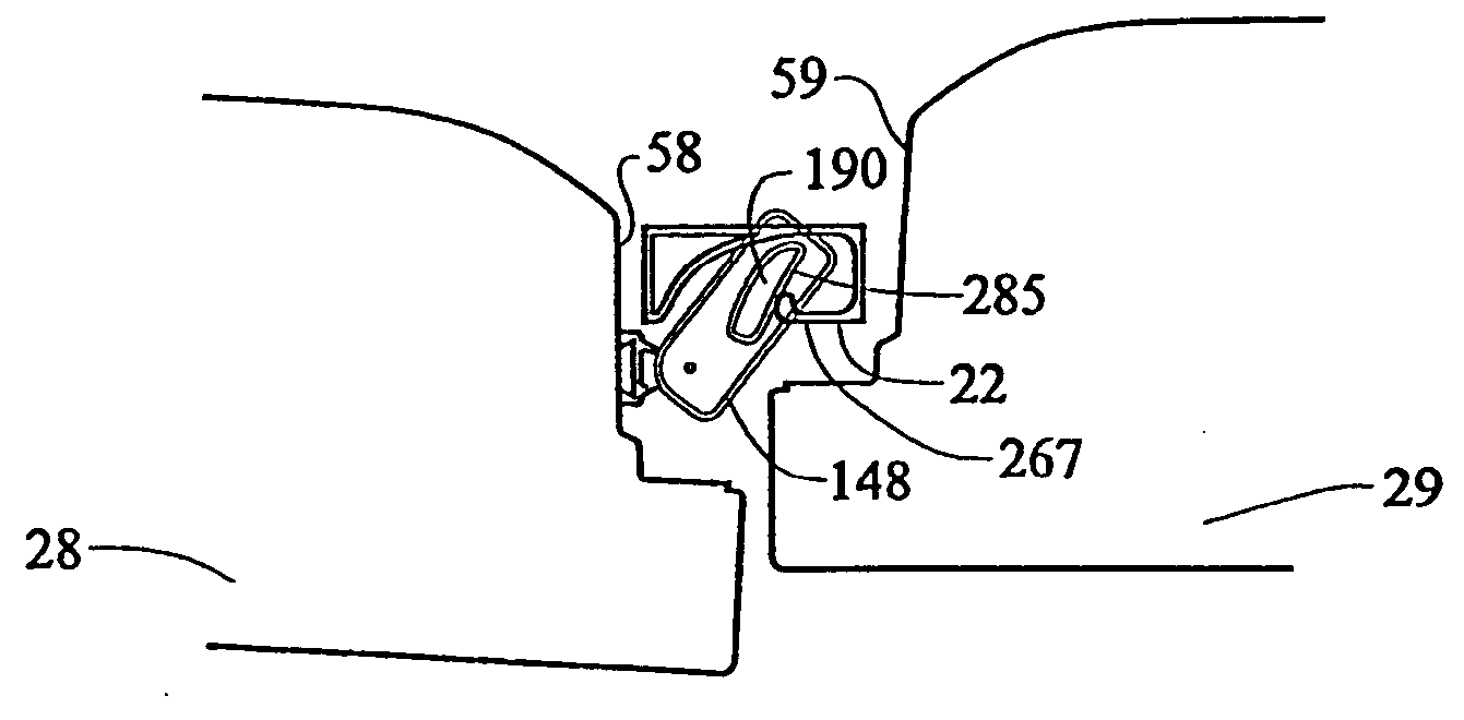
[0011] In further accordance with the most preferred form of the invention, the rotating mullion includes a guide pin member. The guide pin member extends from a top portion of the mullion and rides within a guide element. As the guide pin member travels within the guide element, the rotating mullion moves between the first and second operating positions. Preferably, the rotating mullion includes first and second mating halves each defining a portion of the guide pin member extending therefrom. More preferably, a respective portion of the guide pin member is integrally formed on each of the mating halves. Finally, the rotating mullion is provided with a heating arrangement which, during operation of the refrigeration system, prevents frost and condensation from forming on the rotating mullion.

Problems solved by technology

However, despite all of the desirable features, there exists a drawback with French-style doors in that a mullion bar, which in side-by-side configurations divides the fresh food and freezer compartments, hinders taking goods in and out of the fresh food compartment.
A stationary mullion bar fixed to the refrigerator will limit the size and shape of goods capable of being placed in the compartment, as well as the accessibility to the goods.
While the known retaining and locking mechanisms are functional, they necessarily require additional parts and manufacturing steps which add to the cost and complexity of the overall design.

Method used


Image

  • Refrigerator incorporating french doors with rotating mullion bar
  • Refrigerator incorporating french doors with rotating mullion bar
  • Refrigerator incorporating french doors with rotating mullion bar

Examples


Embodiment Construction

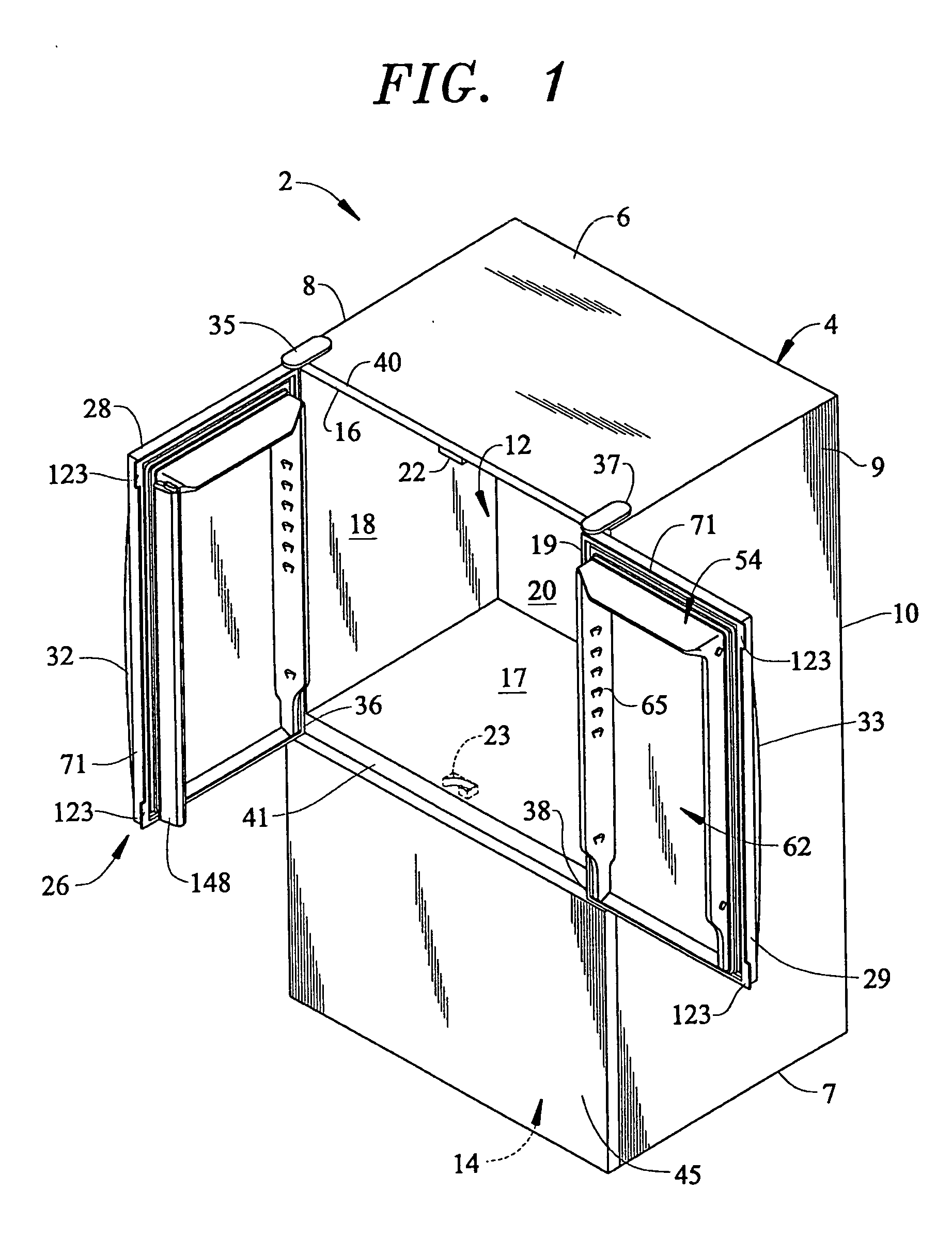
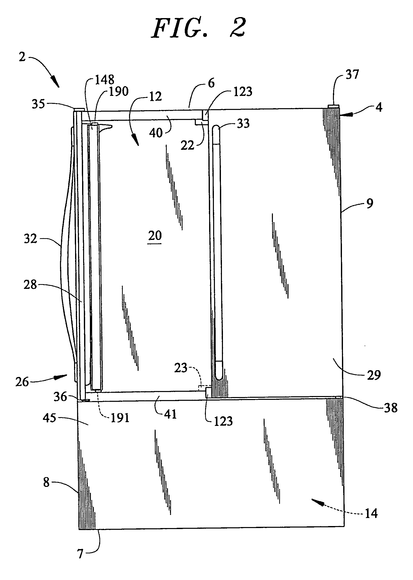
[0024] With initial reference to FIGS. 1 and 2, a bottom-mount refrigerator constructed in accordance with the present invention is generally indicated at 2. Refrigerator 2 is shown to include a cabinet shell 4 having a top wall 6, bottom wall 7, opposing side walls 8 and 9 and a rear wall 10 which combine to form first and second compartments 12 and 14. In the embodiment shown, first or fresh food compartment 12 includes a liner having a top portion 16, a bottom portion 17, opposing side wall portions 18 and 19 and a rear wall portion 20. In addition, a guide element 22, which will be detailed more fully below, is arranged on top portion 16. If desired, a second guide element 23 could be provided on bottom portion 17.

[0025] Refrigerator 2 is provided with an upper door assembly 26 which, in accordance with the preferred form of the invention, is constituted by French-style doors including first and second door members 28 and 29. First and second door members 28 and 29 are provided...


PUM


Abstract

A refrigerator includes French-style doors and a rotating mullion. The rotating mullion is mounted to one of the French-style doors through first and second hinge members. Each of the first and second hinge members include first and second hinge elements having corresponding cam members. The cam members include multiple lobes and extend about hinge pins that define an axis of rotation for the mullion. The multiple lobes actually define first and second detent positions for the rotating mullion. A spring biases the first cam member against the second cam member so that the rotating mullion is positively maintained in either the first or second position. The mullion is formed from mating halves, each including a portion of an integrally formed pin element. The pin element travels within a guide element to automatically rotate the mullion between the first and second positions during use.

Description

BACKGROUND OF THE INVENTION [0001] 1. Field of the Invention [0002] The present invention pertains to the art of refrigerators and, more particularly, to a refrigerator including first and second French-style doors, as well as a rotating mullion bar that enables independent operation of each of the first and second French-style doors. [0003] 2. Discussion of the Prior Art [0004] In general, refrigerators having French-style doors are known. Typically, French-style doors are used in side-by-side configurations to seal fresh food and freezer compartments. With the growing popularity of bottom mount refrigerators, manufacturers are now finding it desirable to provide French-style doors for the upper fresh food compartment. [0005] French-style doors are desirable for a number of reasons, foremost among them is weight reduction. By design, French-style doors divide an opening in half such that each French door is approximately half the weight of a conventional door. In addition, with the...

Claims


Application Information

Patent Timeline
IPC IPC(8): F25D11/02F25D23/02F25D23/08
CPCF25D11/02F25D23/02F25D2400/04F25D2323/021F25D23/087
Inventor CHEKAL, RAYMOND J.KIRCHNER, RICHARD ALLANO'HALLORAN, JEFFREY MICHAELROTTER, CHAD JONATHANSCORPIL, GREG A.STANDEFER, JACK J.STAUFFER, DAVID ALLEN
Owner MAYTAG
Learn More