
Vehicle chassis having a locking device for securing connection between first and second chassis members

a locking device and chassis technology, applied in the field of vehicle chassis, can solve the problems of time-consuming removal of screw fasteners, requiring a significant amount of threading time, etc., and achieve the effect of convenient and rapid connection

Inactive Publication Date: 2005-03-03
SUNPEX TECH
View PDF12 Cites 5 Cited by
  • Summary
  • Abstract
  • Description
  • Claims
  • Application Information

AI Technical Summary

Benefits of technology

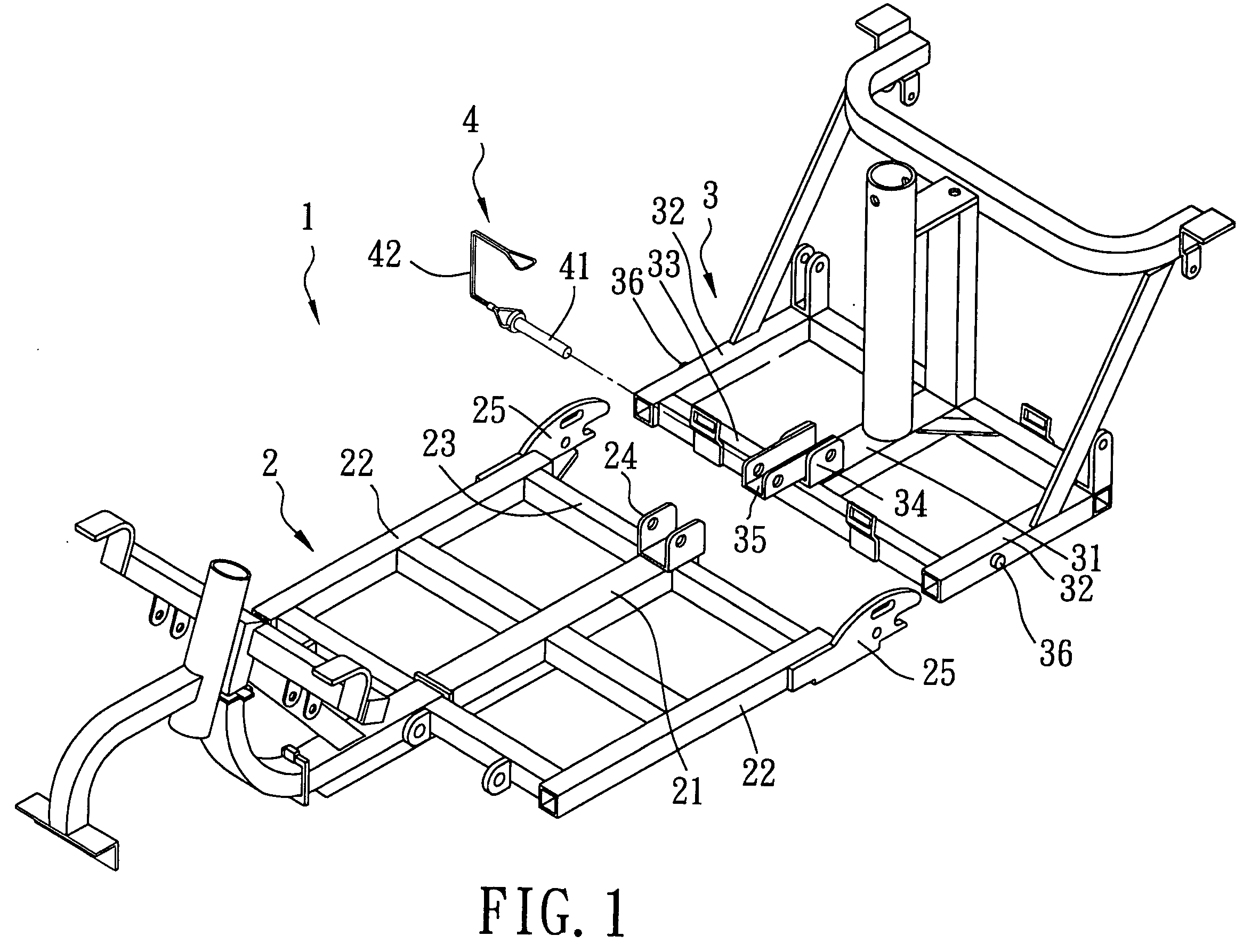
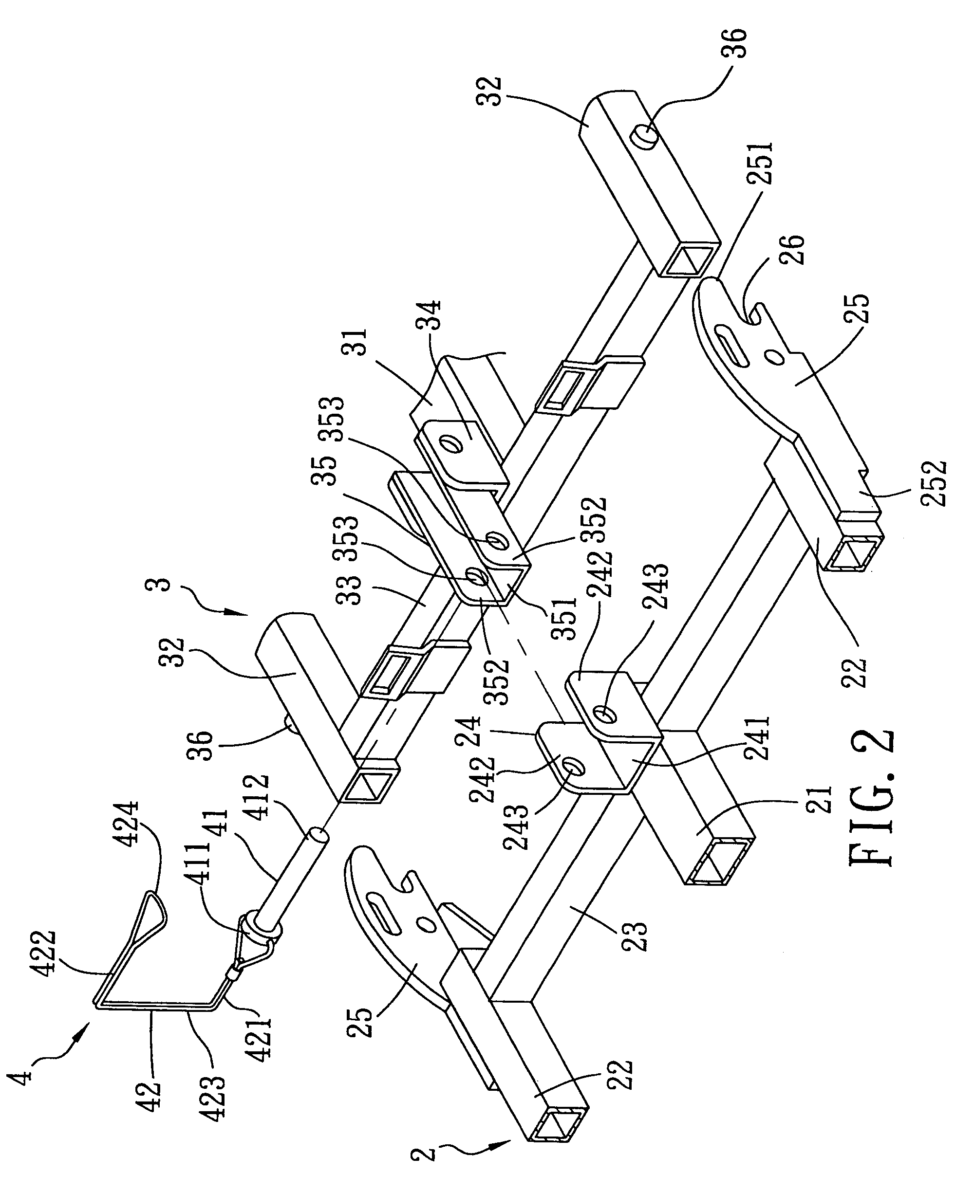
[0006] Therefore, the object of the present invention is to provide a vehicle chassis that has a locking device which permits easy and rapid connection and disconnection of first and second chassis members of the vehicle chassis so as to overcome the aforesaid drawbacks of the prior art.

Problems solved by technology

Although the locking device of the conventional vehicle chassis achieves the purpose of interconnecting the first and second chassis members, there are certain drawbacks associated with the locking device of the conventional vehicle chassis.
One drawback is that it requires a significant amount of time to thread the screw fastener in order to interconnect the first and second chassis members.
Another drawback is that it is also time-consuming to remove the screw fastener in order to disconnect the first chassis member from the second chassis member.

Method used


Image

  • Vehicle chassis having a locking device for securing connection between first and second chassis members
  • Vehicle chassis having a locking device for securing connection between first and second chassis members
  • Vehicle chassis having a locking device for securing connection between first and second chassis members

Examples


first embodiment

[0032]FIG. 5 shows the second preferred embodiment of a vehicle chassis according to this invention. This embodiment differs from the first embodiment in that the vehicle chassis further comprises hook and notch units.

[0033] The hook unit includes a pair of hook connectors 37 fixed respectively on left and right portions of the crossbar 23 of the second chassis member 3. In particular, each of the hook connectors 37 includes horizontal and vertical leg sections 371, 372. The horizontal leg section 371 has a first end portion that is fixed on a respective one of the left and right portions of the crossbar 23, and a second end portion that extends from the first end portion of the horizontal leg section 371 toward the front end portion of the vehicle chassis 1. The vertical leg section 372 extends downwardly from the second end portion of the horizontal leg section 371.

[0034] The notch unit includes a pair of notches 231 formed respectively in left and right portions of the crossbar ...

second embodiment

[0036]FIG. 7 shows the third preferred embodiment of a vehicle chassis according to this invention. This embodiment differs from the second embodiment in that the vehicle chassis further comprises a restricting member 5.

[0037] The restricting member 5 includes a nut 51 formed with a threaded hole, and a screw fastener 52. The horizontal wall 351 of the second connector 35 is formed with a hole therethrough. The hole in the horizontal wall 351 of the second connector 35 is formed in the second end portion of the second connector 35. The nut 51 is mounted on the horizontal wall 351 of the second connector 35 such that the threaded hole in the nut 51 is aligned with the hole in the horizontal wall 351 of the second connector 35.

[0038] With further reference to FIGS. 8 and 9, after connecting the first and second chassis members 2, 3, as best shown in FIG. 8, the screw fastener 52 is threaded through the threaded hole in the nut and is driven such that a tip of the screw fastener 52 ab...


PUM


Abstract

A vehicle chassis includes first and second chassis members, and a locking device. Each of the first and second chassis members includes a connector formed with a hole unit therethrough. The locking device includes a locking pin that extends through the hole units in the connectors, and a resilient retainer that latches releasably to one end of the locking pin.

Description

BACKGROUND OF THE INVENTION [0001] 1. Field of the Invention [0002] The invention relates to a vehicle chassis, more particularly to a vehicle chassis having a locking device for securing connection between first and second chassis members. [0003] 2. Description of the Related Art [0004] A conventional vehicle chassis includes first and second chassis members, and a locking device. The first chassis member includes a connector formed with a threaded hole therethrough. The second chassis member includes a connector formed with a through hole therethrough. The locking device includes a screw fastener passing through the through hole and threaded through the threaded hole in order to interconnect the first and second connectors. [0005] Although the locking device of the conventional vehicle chassis achieves the purpose of interconnecting the first and second chassis members, there are certain drawbacks associated with the locking device of the conventional vehicle chassis. One drawback...

Claims


Application Information

Patent Timeline
Patent Type & Authority Applications(United States)
IPC IPC(8): B62D21/12F16B21/14
CPCB62D21/12
Inventor LIN, SAMUEL
Owner SUNPEX TECH
Learn More