Tool for a knock-on sweep structure

a technology of knock-on sweep and tool, which is applied in the field of tools for removing knock-on sweeps, can solve the problems of affecting the operation the removal of bolts is difficult and time-consuming, and the damage etc., and achieves the effect of convenient quick and easy removal of the retaining device, simple use, and low manufacturing cos

Inactive Publication Date: 2005-03-03
DEERE & CO
View PDF4 Cites 2 Cited by
  • Summary
  • Abstract
  • Description
  • Claims
  • Application Information

AI Technical Summary

Benefits of technology

[0006] It is therefore an object of the present invention to provide an improved sweep removal tool that overcomes most or all of the above-mentioned problems. It is another object to provide such an improved tool which is simple to use and inexpensive to manufacture and which facilitates quick and easy removal of the sweep. It is yet another object to provide such a tool having improved retainer depressor alignment and retainer protection.

Problems solved by technology

When the tool in such an assembly has to be replaced because of wear or damage, the bolts must be removed.
Wear and corrosion of the bolts substantially hinders removal and often makes the replacement a difficult and time-consuming task.
Retaining devices have suffered from one or more problems, including need for additional parts and the loss of sweeps when encountering high removal forces during transport and during rebounding of the shank from a tripped position.
The tool shown in the U.S. Pat. No. 6,585,058 is not entirely satisfactory for use with the improved assembly.
The claw construction limit accurate and repeatable placement of the tool for optimum stability and interaction with the sweep.
If the tool is not accurately placed on the sweep stem, the extension may not enter the sweep opening or portions of the tool such as the extension or the claws can actually contact and damage the spring as the sweep is driven off the shank.
The extension can transfer damaging forces to the spring as the tool is impacted during sweep removal.
If the depressor contacts the spring at the coil location, retainer depression is difficult or impossible.
Under some conditions, the spring can be improperly contacted and deformed by the extension so that sweep retention is compromised.

Method used


Image

  • Tool for a knock-on sweep structure
  • Tool for a knock-on sweep structure
  • Tool for a knock-on sweep structure

Examples


Embodiment Construction

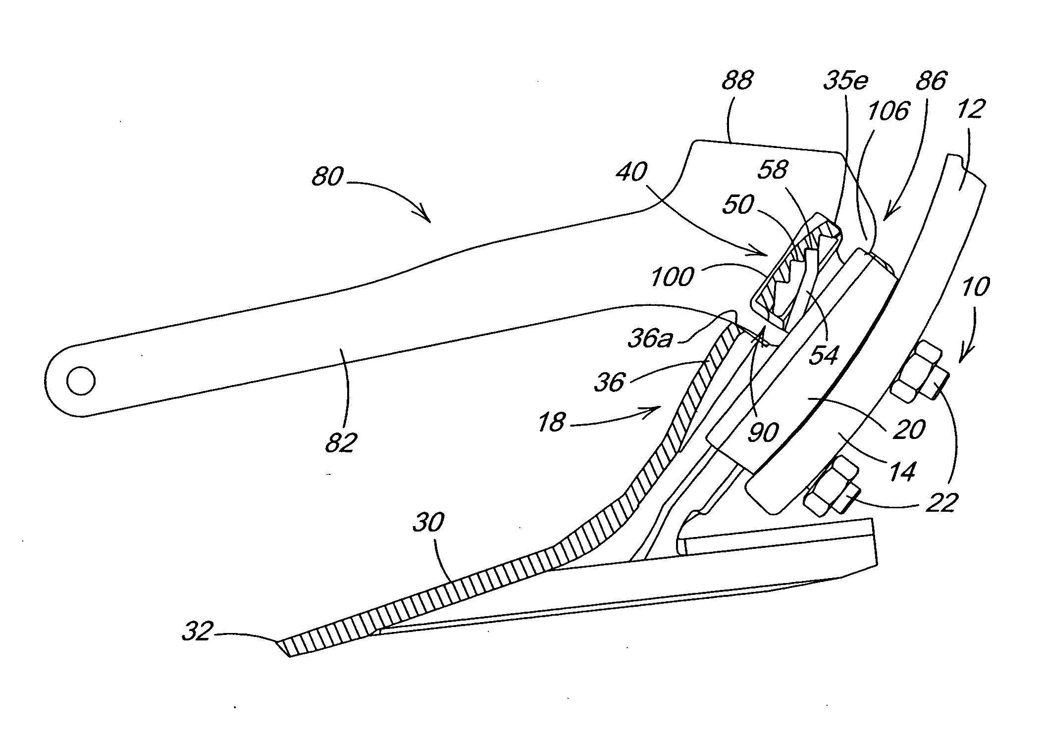
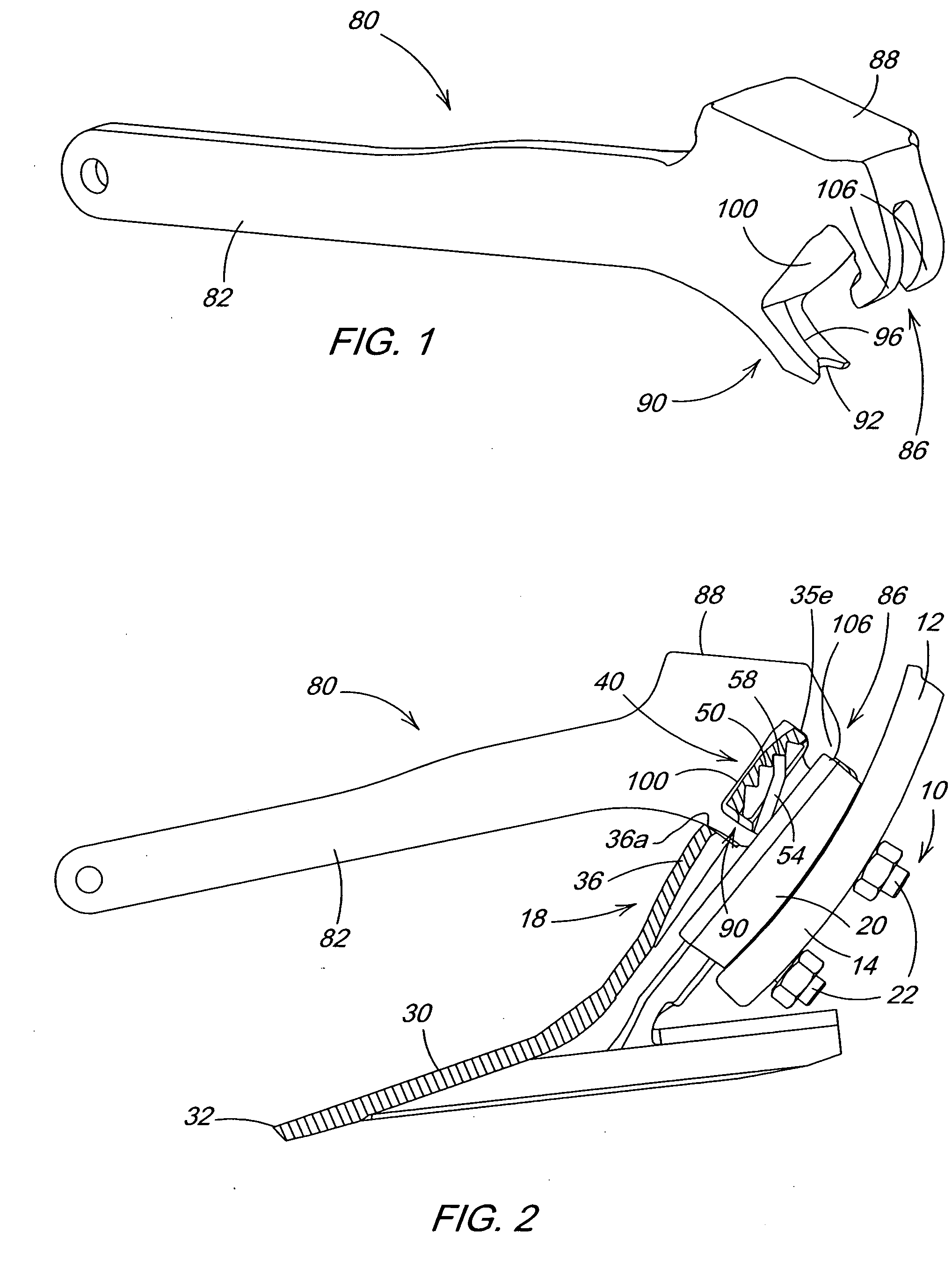
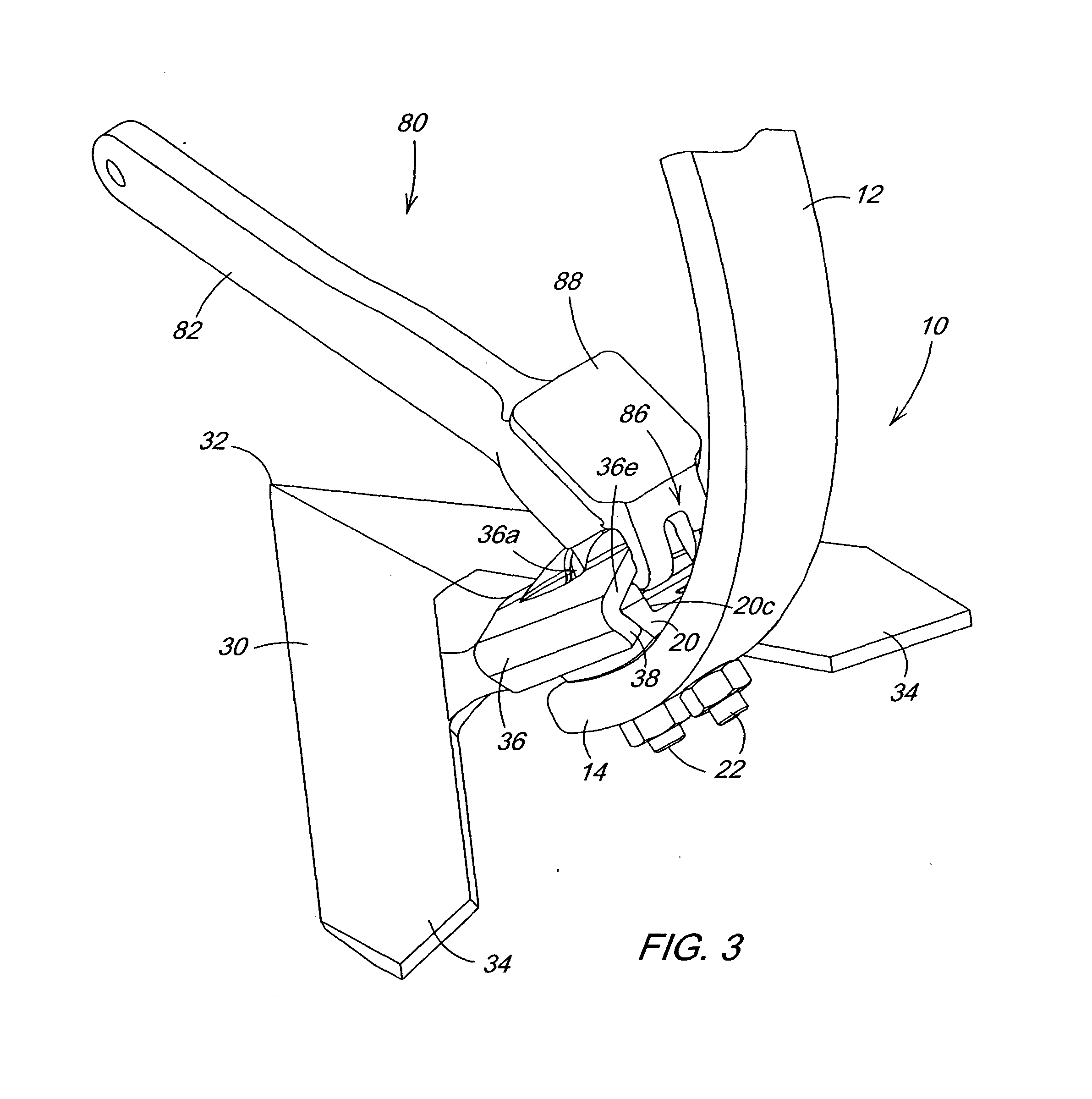
[0017] Referring now to FIGS. 2-4, therein is shown the lower portion of a spring trip shank assembly 10 including a shank 12 having a lower tool-mounting end 14 supporting a knock-on sweep assembly 18. The assembly 18 includes a wedge-shaped adapter bracket or sweep support 20 having an aft face conforming to the forward face of the end 14. The support 20 is secured to the end 14 by two plow bolts 22 (FIG. 2). An earthworking tool 30, shown as a sweep in FIGS. 2-4, includes a forwardmost tip or point 32 and opposed wing portions 34 diverging outwardly in the rearward direction. An downwardly and rearwardly concave sweep mounting portion or stem 36 includes an aperture 36a and edges 38 which wrap partially around the bracket 20. The portion 36 provides a wedge fit between the tool 30 and the lower end 14 of the shank 12 when the tool 30 is in the final mounted position. Although a cultivator sweep is shown, the tool 30 can be any type of replaceable earthworking tool for various typ...


PUM

PropertyMeasurementUnit
diameteraaaaaaaaaa
impact forcesaaaaaaaaaa
notched areaaaaaaaaaaa

Abstract

A sweep removal tool includes a pair of claws with angled surfaces conforming to the top edge of the sweep stem to locate the tool and help distribute sweep removal impact forces. A retainer depressor centered below the claws moves the retainer to a release position and slides between the angled surfaces during sweep removal. The depressor shape assures desired tine contact, even when the sweep is at an extreme position in the range of possible mounted positions, while preventing damaging contact as the depressor moves relative to the retainer during sweep removal. A curved surface extends between the claws and the depressor and facilitates free pivoting of the tine about the claw contact points to depress the retainer. The tool bottoms against the sweep when the depressor is moved to the release position to prevent retained damage from removal impact forces.

Description

FIELD OF THE INVENTION [0001] The present invention relates generally to tillage tools and, more specifically, to a tool for removing a knock-on sweep from the end of a shank. BACKGROUND OF THE INVENTION [0002] Standard assemblies for implements such as chisel plows and field cultivators typically include a spring trip shank assembly extending downwardly to a tool-receiving end which mounts a shovel, point or sweep. Previously available mounting structure included bolts extending through holes in the tool and the shank to secure the tool. When the tool in such an assembly has to be replaced because of wear or damage, the bolts must be removed. Wear and corrosion of the bolts substantially hinders removal and often makes the replacement a difficult and time-consuming task. [0003] Numerous solutions to the problem of easily and quickly replacing worn elements such as sweeps on shanks have been developed over the years, including adapter brackets providing a self-locking fit with a mat...

Claims


Application Information

Patent Timeline
Patent Type & Authority Applications(United States)
IPC IPC(8): A01B35/22B25B27/00
CPCA01B35/225Y10T29/53896B25B27/00
Inventor POUTRE, BENOIT JOCELYNPECK, DONALD RAYBEECK, MARK DONALD
Owner DEERE & CO
Why Eureka
Try Eureka