
Combined device comprising a venous blood reservoir and a cordiotomy reservoir in an extracorporeal circuit

a combined device and cordiotomy technology, applied in the field of surgical procedures, can solve the problems of large surface area of such devices which come into contact with blood, blood becomes susceptible to damage or coagulation, and the device is known to have certain disadvantages, so as to eliminate the risk of reverse filtration and minimize blood contact

Inactive Publication Date: 2005-02-24
SORIN GRP ITAL SRL
View PDF3 Cites 1 Cited by
  • Summary
  • Abstract
  • Description
  • Claims
  • Application Information

AI Technical Summary

Benefits of technology

The present invention provides a combined device with both a venous blood reservoir and a cardiotomy reservoir. The device minimizes blood contact with large surface areas and eliminates the risk of reverse filtration. The lower reservoir is used as the venous reservoir and the upper reservoir is used as the cardiotomy reservoir. The device includes a housing with a partition that separates the two reservoirs. Each of the blood inlet connectors is positioned so that blood entering the device flows through a defoaming substance and a filter. The partition has at least two ducts that project upward into the cardiotomy reservoir and reach different elevations therein. The technical effects of this invention are that it allows for the option of integrating venous and cardiotomy blood if surgical conditions or requirements warrant, and it minimizes the risk of complications during surgery.

Problems solved by technology

These devices, however, are known to have certain disadvantages.
For example, the surface area of such devices which comes into contact with the blood is relatively large.
As a result, the blood becomes susceptible to damage or coagulation.
Additionally, even under relatively normal operating conditions, retrograde blood flow may be induced, causing the blood to be reverse filtered.
This is particularly problematic if only venous blood is being collected, because the retrograde flow causes the blood to be sequestered within the cardiotomy filter, thereby reducing the volume of blood available for oxygenation and recirculation to the patient.

Method used


Image

  • Combined device comprising a venous blood reservoir and a cordiotomy reservoir in an extracorporeal circuit
  • Combined device comprising a venous blood reservoir and a cordiotomy reservoir in an extracorporeal circuit
  • Combined device comprising a venous blood reservoir and a cordiotomy reservoir in an extracorporeal circuit

Examples


Embodiment Construction

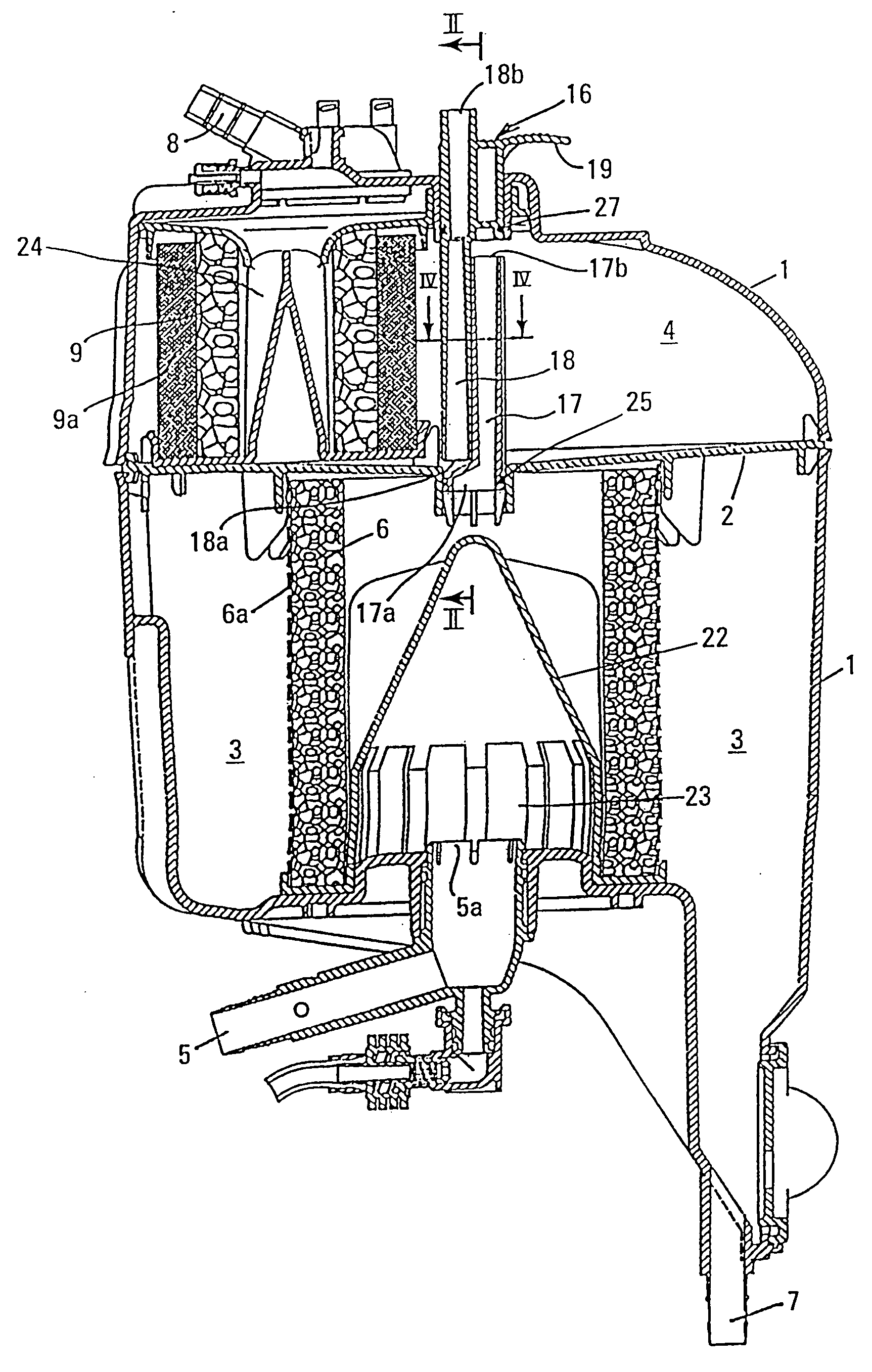
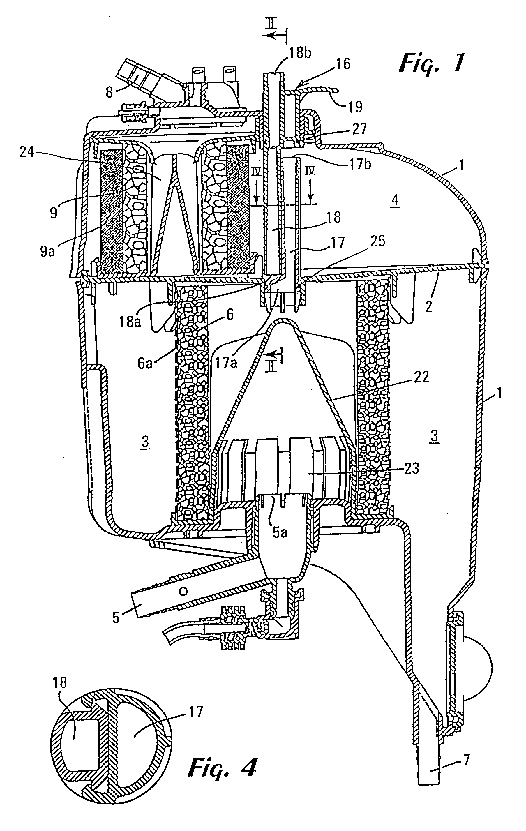
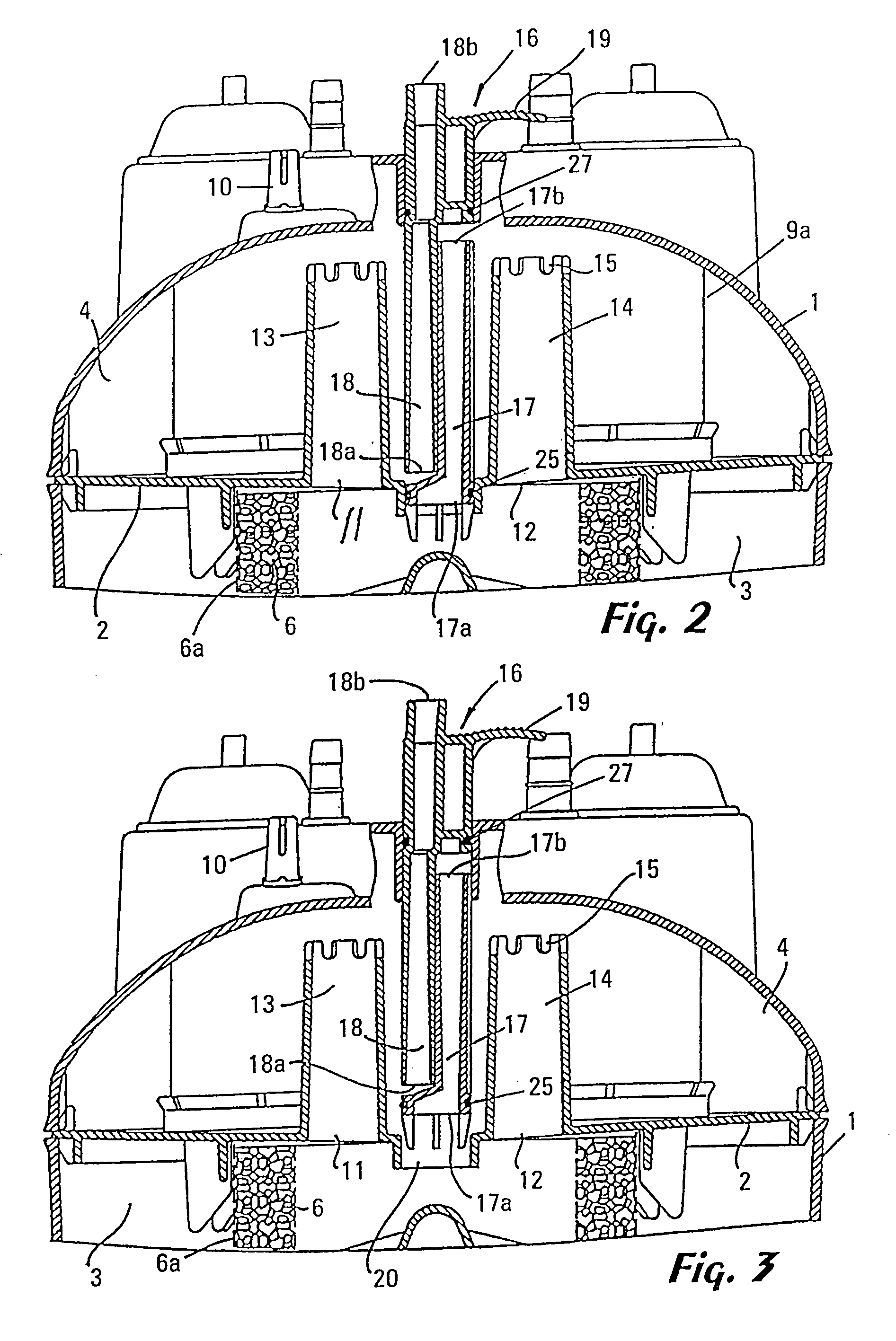
[0014] One embodiment of the device of the present invention is depicted in FIGS. 1-4. Regarding FIGS. 2 and 3, and for the sake of clarity, a view of the device taken along plane II-II of FIG. 1 is shown. In FIGS. 2 and 3, the column 16 has been rotated 90° into the page with respect to its position shown in FIG. 1. With reference to the above Figures, the reference numeral 1 designates a housing of the device and the reference numeral 2 designates a partition which divides the space enclosed by the housing 1 into a venous reservoir 3, and a cardiotomy reservoir 4. The housing is preferably formed of a transparent polymer to allow the interior of the device to be viewed by an operator. Numerous transparent, medically useful polymers are known to those having ordinary skill in the art.

[0015] The venous reservoir 3 is provided with a venous inlet connector 5, terminating at 5a, for the venous blood. Venous blood entering the venous reservoir 3 through the venous inlet connector 5 en...


PUM

PropertyMeasurementUnit
aperture sizeaaaaaaaaaa
blood flow rateaaaaaaaaaa
blood pressureaaaaaaaaaa

Abstract

A combined device having a reservoir for venous blood and a reservoir for cardiotomy blood is disclosed. The device is characterized in that the venous reservoir is separated from the cardiotomy reservoir by a partition which includes a plurality of apertures. The apertures are in fluid communication with a plurality of ducts and passageways which are configured to provide various modes of operation depending upon whether, for the particular surgical conditions, it is desired to mix venous and cardiotomy blood, or to isolate those blood pools from each other.

Description

[0001] This application is a continuation of application Ser. No. 09 / 952,093, filed Sept. 11, 2001, which is a continuation of application Ser. No. 08 / 888,777, filed Jul. 7, 1997, now U.S. Pat. No. 6,287,270, the contents of which are hereby incorporated herein by reference.FIELD OF THE INVENTION [0002] The present invention is in the field of devices for use in surgical procedures. More particularly, the present invention relates to a device having both a venous blood reservoir and a cardiotomy reservoir for use in an extracorporeal circuit. BACKGROUND OF THE INVENTION [0003] Many surgical operations involve circulating the blood of a patient through an extracorporeal circuit. In particular, many open-heart surgical procedures require that the patient's heart be stopped, and that various biological functions (i.e., blood circulation and oxygenation) be performed mechanically by various devices included in the extracorporeal circuit. In addition to a pump and to the tubing through w...

Claims


Application Information

Patent Timeline
Patent Type & Authority Applications(United States)
IPC IPC(8): A61M1/10A61M1/36G01N27/90A61J1/05
CPCA61M1/3627A61M1/3632G01N27/904G01N27/902
Inventor FINI, MASSIMO
Owner SORIN GRP ITAL SRL
Learn More